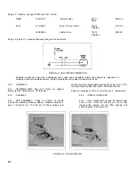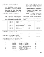
Page 4-1, add new paragraphs 4-6A and 4-6B to read:
4-6A.
PEN SYSTEM
4-6B.
The pen assembly consists of a drum type
reservoir resting in a pivot mount which moves along
the carriage arm. A rigid capillary tube feedline leads
from the reservoir to the pen point. Because of the
capillary process, rack mounted (vertical) models
write equally well as the table models. The pen
should never be allowed to run dry.
Page 5-3, add new paragraphs 5-18A and 5-18B to read:
5-18A.
PEN MAINTENANCE
5-18B.
Pen writing failures may be caused by dried
ink, sediment, air bubbles in feed line, or general
neglect. Dirt and ink sediment cause the most
difficulty. Dried ink forms brittle crust particles which,
together with dirt, build up in the supply line until the
ink stops flowing. Pen assemblies should be cleaned
thoroughly every two to four weeks. Clean by soaking
in alcohol or hot water. Clogging during operation
may be cleared by one or more of the following steps:
a.
Using the furnished syringe, apply air pressure to
the reservoir's ink filler hole.
b.
Soak pen assembly in alcohol or hot water.
c.
Internally clean tip by inserting the stiff wire
supplied in accessory kit.
d.
Prior to extended storage, flush and clean pen.
CAUTION
Care must be taken not to touch pen
tip with fingers or any greasy
substance.
Page 6-6, Table 6-2, Mechanical, Electric, add 17999-15126,
Pen Cleaning Wire, H-P, 17999-15126.
Page 6-6, Table 6-2, Accessory Kit, Paper, Ink, change to read
as follows:
17999-09423
Syringe (Pen filler)
H-P
17999-09473
9260-0128
Ink, Red
9260-0127
Ink, Blue
9270-1006
Chart Paper, Standard (heavy)
Gubelman
H-10070/A
9270-1007
Chart Paper, Standard (light)
Gubelman
L-10070/A
9270-1023
Chart Paper, Metric (heavy)
Gubelman
9270-1027
Chart Paper, Metric (light)
Gubelman
07035-80630
Pen Assy
H-P
07035-80630
07035-81030
Pen Accessory Kit
H-P
07035-81030
5950-2587
Maintenance brochure
H-P
5950-2587
Page 6-7, Table 6-3, Spare Parts, change K401 to:
07035-60140
Solenoid, Pen Lift
H-P
07035-60140
07035-60120
Plunger Assy, Solenoid
H-P
07035-60120
Page 6-7, Table 6-3, Spare Parts, delete Pen Holder, add:
07035-80630
Pen Assembly
H-P
07035-80630
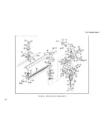
Page 6-10, Figure 6-2 (Illustration) is changed as shown in Figure 8-5.
Page 6-11, Figure 6-2 (Legend) make the following changes:
12
14600722
Spring, Pen Lift
Superior Spring
47
07035-41820
Block, Pen Arm
H-P
48
0703560185
Pen Scale Assy - Blank Scale
H-P
07035-60186
Pen Scale Assy - English Scale
H-P
07035-60250
Pen Scale Assy - Metric Scale
H-P
54
07035-61120
Pen Holder Assy (all Serial Prefixes
H-P
before 803)
07035-60070
Pen Holder Assy (Serial Prefix 803 and
H-P
later without disposable pen)
56
07035-61410
Pen Lift Assy
H-P
58
07035-60140
Solenoid Assy (Below S/P 826 requires
H-P
index point 07005-00730)
60
07035-62210
Plunger, Solenoid Assy
H-P
61
07035-80630
Pen Assy
H-P
8-5
Содержание HP-7035B
Страница 1: ...TECHNICAL MANUAL HEWLETT PACKARD MODEL HP 7035B ...
Страница 9: ...FIGURE 1 4 DIMENSION DRAWING FIGURE 1 5 ACCESSORIES 1 3 ...
Страница 12: ...FIGURE 1 7 TYPICAL FREQUENCY RESPONSE INPUT FILTER FIGURE 1 8 TYPICAL DYNAMIC RESPONSE 1 6 ...
Страница 14: ...FIGURE 2 1 WING BRACKET INSTALLATION FIGURE 2 2 STACKED CONFIGURATION 2 2 ...
Страница 16: ...FIGURE 3 1 FRONT PANEL CONTROLS 7035B AND 7035B 001 MODELS 3 2 ...
Страница 20: ...FIGURE 4 1 BLOCK DIAGRAM FIGURE 4 2 DETAILED BLOCK DIAGRAM 4 2 ...
Страница 48: ...TM 11 6625 2850 14 P FIGURE 6 1 EXPLODED VIEW CABINET 6 9 ...
Страница 49: ...TM 11 6625 2850 14 P FIGURE 6 2 EXPLODED VIEW CARRIAGE ARM SHEET 1 OF 2 6 10 ...
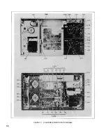
Страница 58: ...FIGURE 7 1 COMPONENT IDENTIFICATION FRAME 7 8 ...
Страница 59: ...TM 11 6625 2850 14 P Figure 7 2 Component Identification Circuit Board 7 9 ...
Страница 60: ...TM 11 6625 2850 14 P Figure 7 3 Schematic Model 7035B D 07035 92550 7 10 ...
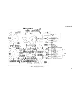
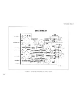
Страница 62: ...TM 11 6625 2850 14 P FIGURE 8 1 COMPONENT IDENTIFICATION CIRCUIT BOARD 8 2 ...
Страница 66: ...TM 11 6625 2850 14 P FIGURE 8 5 EXPLODED VIEW CARRIAGE ARM 8 6 ...

