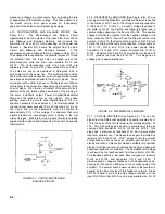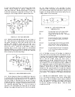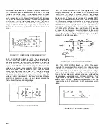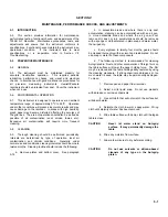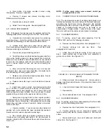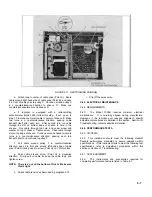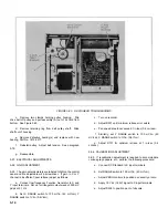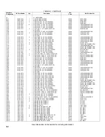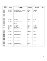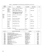
TABLE 5-1. RECOMMENDED TEST EQUIPMENT
1. HP MODEL 740B DC VOLTAGE STANDARD
2. HP MODEL 3310A FUNCTION GENERATOR
3. HP MODEL 410C or 427A DC VOLTMETER
4. HP MODEL 202A LOW FREQUENCY FUNCTION
GENERATOR
5-53. INITIAL CHECKS
5-54. To perform initial performance checks:
a.
Set 115/230 selector switch to appropriate power
source.
b.
Connect power cable.
c.
Install pen and paper.
d.
Position POWER/SERVO toggle switch to ON-ON.
e.
Position CHART toggle switch to HOLD. Paper is
held down securely.
f.
Position PEN toggle switch to DOWN.
g.
Connect DC Standard to high and low (+ and -) Y-axis
inputs.
h.
Apply positive dc voltage. Pen moves upscale.
i.
Return pen to zero position.
j.
Disconnect DC Standard from Y inputs. Connect to X
inputs.
k.
Apply positive dc voltage. Pen moves across
recording area.
5-55. Y-AXIS ACCURACY AND LINEARITY
a.
Connect DC Standard to Y input terminals.
b.
Place pen at exactly zero on Y-axis and at 5 inches
(12. 5 cm) on X-axis.
c.
Apply 0.7 volt to Y input terminals.
d.
Pen should stop at 7 inches (18 cm) within ±0.014 in.
(0.34 mm).
e.
If pen does not stop within tolerance, adjust
calibration control (R-126).
f.
Reduce voltage applied in steps of 0.1V at each step.
g.
After each step, pen should stop at 1 in. (2 cm)
intervals within 0.014 in. (0.34 mm).
5-56. X-AXIS ACCURACY AND LINEARITY
a.
Connect DC Standard to X input terminals.
b.
Place pen at exactly zero on X-axis and at 3.5 in. (9
cm) on Y-axis.
c.
Apply 1 volt to X input terminals.
d.
Pen should stop at 10 inches (25 cm) within ±0.020
in. (0.5 mm).
e.
If pen does not stop within tolerance, adjust
calibration control (R226).
f.
Reduce voltage applied in steps of 0.1V at each step.
g.
After each step, pen should stop at 1 in. (2 cm)
intervals within 0.020 in. (0.5 mm).
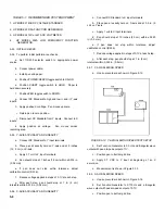
5-57. Y-AXIS SLEWING SPEED
a.
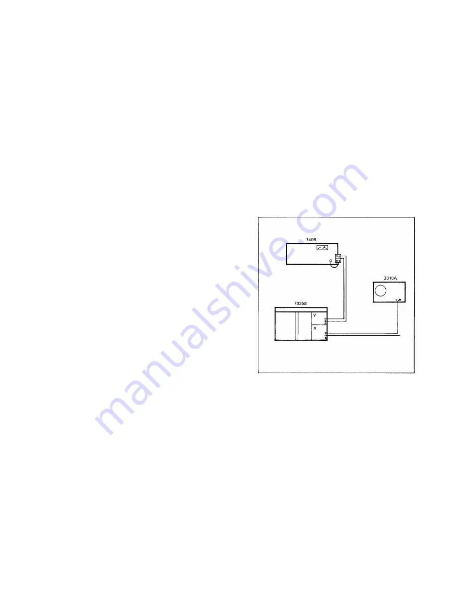
Hook up recorder as shown in Figure 5-12.
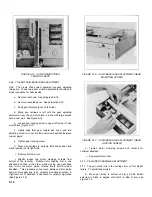
FIGURE 5-12. Y-AXIS SLEWING SPEED TEST SETUP
b.
Set Function Generator to 0.5 Hz and triangular wave
output with peak-to-peak output of 1V.
c.
Position pen to bottom grid line.
d.
Apply 0.7 VDC to Y input at beginning of an X
excursion.
e.
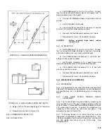
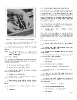
Measurement is shown in Figure 5-13.
5-58. X-AXIS SLEWING SPEED
a.
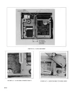
Hook up recorder as shown in Figure 5-14.
b.
Set Function Generator to 0.715 Hz and a triangular
wave output with peak-to-peak output of 0.7V.
c.
Position pen to bottom grid line.
5-8
Содержание HP-7035B
Страница 1: ...TECHNICAL MANUAL HEWLETT PACKARD MODEL HP 7035B ...
Страница 9: ...FIGURE 1 4 DIMENSION DRAWING FIGURE 1 5 ACCESSORIES 1 3 ...
Страница 12: ...FIGURE 1 7 TYPICAL FREQUENCY RESPONSE INPUT FILTER FIGURE 1 8 TYPICAL DYNAMIC RESPONSE 1 6 ...
Страница 14: ...FIGURE 2 1 WING BRACKET INSTALLATION FIGURE 2 2 STACKED CONFIGURATION 2 2 ...
Страница 16: ...FIGURE 3 1 FRONT PANEL CONTROLS 7035B AND 7035B 001 MODELS 3 2 ...
Страница 20: ...FIGURE 4 1 BLOCK DIAGRAM FIGURE 4 2 DETAILED BLOCK DIAGRAM 4 2 ...
Страница 48: ...TM 11 6625 2850 14 P FIGURE 6 1 EXPLODED VIEW CABINET 6 9 ...
Страница 49: ...TM 11 6625 2850 14 P FIGURE 6 2 EXPLODED VIEW CARRIAGE ARM SHEET 1 OF 2 6 10 ...
Страница 58: ...FIGURE 7 1 COMPONENT IDENTIFICATION FRAME 7 8 ...
Страница 59: ...TM 11 6625 2850 14 P Figure 7 2 Component Identification Circuit Board 7 9 ...
Страница 60: ...TM 11 6625 2850 14 P Figure 7 3 Schematic Model 7035B D 07035 92550 7 10 ...
Страница 62: ...TM 11 6625 2850 14 P FIGURE 8 1 COMPONENT IDENTIFICATION CIRCUIT BOARD 8 2 ...
Страница 66: ...TM 11 6625 2850 14 P FIGURE 8 5 EXPLODED VIEW CARRIAGE ARM 8 6 ...

