SECTION III
OPERATING INSTRUCTIONS
3-1.
OPERATING REQUIREMENTS
3-2.
GENERAL
3-3.
The basic function of the Model 7035B Recorder is to
produce graphic tracings showing the relationship between two
variable functions. Slowly varying dc signals representing
these functions are applied to the input terminals of the
respective axes of the instrument, and its controls adjusted so
that the resulting graph will cover the desired scope of
operation.
CAUTION
Before attempting to operate this
instrument the user should study the
following paragraphs.
3-4.
CONTROLS, CONNECTORS, AND INDICATORS
3-5.
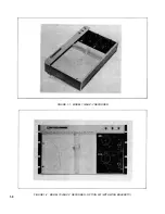
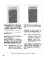
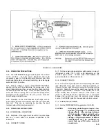
The front and rear panel controls, connectors, and
indicators are depicted and explained in
Figures 3-1 and 3-2.
3-6.
ELECTRICAL REQUIREMENTS
3-7.
OPERATING POWER
3-8. The line power supplied to the recorder should be either
115 or 230 volts 10%, 50 to 60 Hz, single phase. A voltage
conversion switch, see Figure 3-2, must be set to correspond
to the available supply voltage. For 115 Vac use a 3/4 amp
fuse. For 230 Vac use a 3/8 amp fuse.
3-9. INPUT SIGNALS
3-10. The recorder input terminals (+ and -) must be supplied
with a dc signal on each axis. This signal should be in direct
proportion to the actual function unless a special relationship is
required, such as the logarithmic value of the input voltage.
These signals must vary at a rate within the response
capabilities of the instrument and have amplitudes within its
scale ranges. If an excessive amount of ac noise is present in
the input signals, the response of the recorder may become
sluggish and erratic or oscillatory.
CAUTION
Do not directly apply signals in excess of
250 volts on the X-axis or 175 volts on the
Y-axis.
3-11. GROUNDING
3-12. For optimum performance, the third prong of the ac
power cord must be grounded. When operating from
ungrounded power sources, adequate grounding is mandatory.
3-13. RECORDING INPUT CONNECTIONS
3-14. Input terminals for each axis are located on the front
panel adjacent to the corresponding range switches. Front
panel terminals will accept either "banana" plugs or open
wires.
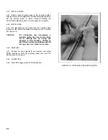
3-15. CONNECTION TECHNIQUES FOR THE GUARD
SHIELD
3-16. Connect the recorder's guard shield in one of the
following ways:
a.
To the SOURCE ground when:
1.
Operating on low level ranges
2.
When ac noise pickup is a problem.
b.
To the negative input using the convenient shorting
straps when conditions 1 and 2 do not exist.
CAUTION
Do not leave the guard shield
disconnected or floating. Tighten guard
strap securely.
3-17. MAXIMUM ALLOWABLE SOURCE IMPEDANCE
3-18. No restrictions except on fixed 1mv/in. (0.4 mv/cm)
range. Up to 20k ohm source impedance will not appreciably
alter the recorder's performance. Higher source impedance
will cause an increase in dead zone and a decrease in pen
speed. Values up to approximately 100k may be compensated
for by adjusting the servo amplifier gain adjustment (front
panel).
3-1
Содержание HP-7035B
Страница 1: ...TECHNICAL MANUAL HEWLETT PACKARD MODEL HP 7035B ...
Страница 9: ...FIGURE 1 4 DIMENSION DRAWING FIGURE 1 5 ACCESSORIES 1 3 ...
Страница 12: ...FIGURE 1 7 TYPICAL FREQUENCY RESPONSE INPUT FILTER FIGURE 1 8 TYPICAL DYNAMIC RESPONSE 1 6 ...
Страница 14: ...FIGURE 2 1 WING BRACKET INSTALLATION FIGURE 2 2 STACKED CONFIGURATION 2 2 ...
Страница 16: ...FIGURE 3 1 FRONT PANEL CONTROLS 7035B AND 7035B 001 MODELS 3 2 ...
Страница 20: ...FIGURE 4 1 BLOCK DIAGRAM FIGURE 4 2 DETAILED BLOCK DIAGRAM 4 2 ...
Страница 48: ...TM 11 6625 2850 14 P FIGURE 6 1 EXPLODED VIEW CABINET 6 9 ...
Страница 49: ...TM 11 6625 2850 14 P FIGURE 6 2 EXPLODED VIEW CARRIAGE ARM SHEET 1 OF 2 6 10 ...
Страница 58: ...FIGURE 7 1 COMPONENT IDENTIFICATION FRAME 7 8 ...
Страница 59: ...TM 11 6625 2850 14 P Figure 7 2 Component Identification Circuit Board 7 9 ...
Страница 60: ...TM 11 6625 2850 14 P Figure 7 3 Schematic Model 7035B D 07035 92550 7 10 ...
Страница 62: ...TM 11 6625 2850 14 P FIGURE 8 1 COMPONENT IDENTIFICATION CIRCUIT BOARD 8 2 ...
Страница 66: ...TM 11 6625 2850 14 P FIGURE 8 5 EXPLODED VIEW CARRIAGE ARM 8 6 ...

