Honeywell
21
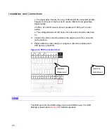
Figure 3-1 Alarm Input and Output of HSVR-04 (Left) and HSVR-16
(Right)
Parameter
Grounding Alarm
Ground line
Alarm Input
HSVR-04: 1, 2, 3, 4 become valid in low voltage; 5, 6, 7, 8 are not
effective.
HSVR-16: 1-16 become valid in low voltage.
Relay Output NO C
1-NO C, 2-NO C, 3-NO C Three Normal Open activation outputs.
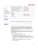
RS-485 A/B
RS-485 communication port. They are used to control devices
such as PTZ. Please parallel connect 120
Ω
between A/B cables if
there are too many PTZ decoders.
Alarm Input Port
4-ch (HSVR-04) / 16-ch (HSVR-16)grounding alarm inputs. (Normal open
or Normal close type)
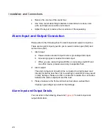
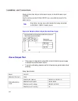
Please parallel connect COM end and GND end of the alarm detector
(Provide external power to the alarm detector).
Please parallel connect the ground of the DVR and the ground of the alarm
detector.
Содержание HSVR-04
Страница 2: ......
Страница 47: ...Honeywell 39 Figure 4 14 Motion Detection Zone Setting Figure 4 15 PTZ Activation Setting ...
Страница 100: ...Understanding of Menu Operations and Controls 92 Figure 5 38 The Shutdown Menu ...
Страница 103: ...Honeywell 95 Figure 6 2 The Internet Options Window ...
Страница 115: ...Honeywell 107 Figure 6 21 HDD Information Menu Log Here you can view system log See Figure 6 22 ...
Страница 130: ...Web Client Operation 122 Figure 6 37 The NTP Setup Menu Alarm Alarm setup interface is shown as in Figure 6 38 ...
Страница 133: ...Honeywell 125 Figure 6 39 The Detection Setup Menu Figure 6 40 The Detection Zone Setup ...
Страница 142: ...Web Client Operation 134 Figure 6 47 The Auto Maintenance Menu Abnormity The abnormity interface is shown as below ...

