Overview and Controls
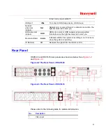
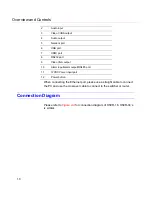
10
2
Audio input
3
Video CVBS output
4
Audio output
5
Network port
6
USB port
7
HDMI port
8
RS232 port
9
Video VGA output
10
Alarm input/alarm output/RS485 port
11
12VDC Power input port
12
Power button
When connecting the Ethernet port, please use a straight cable to connect
the PC and use the crossover cable to connect to the switcher or router.
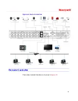
Connection Diagram
Please refer to
Figure 2-4
for connection diagram of HSVR-16. HSVR-04’s
is similar.
Содержание HSVR-04
Страница 2: ......
Страница 47: ...Honeywell 39 Figure 4 14 Motion Detection Zone Setting Figure 4 15 PTZ Activation Setting ...
Страница 100: ...Understanding of Menu Operations and Controls 92 Figure 5 38 The Shutdown Menu ...
Страница 103: ...Honeywell 95 Figure 6 2 The Internet Options Window ...
Страница 115: ...Honeywell 107 Figure 6 21 HDD Information Menu Log Here you can view system log See Figure 6 22 ...
Страница 130: ...Web Client Operation 122 Figure 6 37 The NTP Setup Menu Alarm Alarm setup interface is shown as in Figure 6 38 ...
Страница 133: ...Honeywell 125 Figure 6 39 The Detection Setup Menu Figure 6 40 The Detection Zone Setup ...
Страница 142: ...Web Client Operation 134 Figure 6 47 The Auto Maintenance Menu Abnormity The abnormity interface is shown as below ...


