


Installation and Connections
18
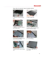
After completing HDD installation, please check the connection of the data
ribbon and power cord.
Connecting Power Supply
Please check whether the input voltage and device power button match.
We recommend you use UPS to guarantee steady operation, DVR life span,
and other peripheral equipments’ operation such as cameras.
Connecting Video Input and Output Devices
Connecting Video Input
The video input interface is BNC. The input video format includes:
PAL/NTSC BNC(1.0V
P- P
,
75
Ω
).
The video signal should comply with your national standards.
The input video signal should have high SNR, low distortion, low
interference, natural color and suitable lightness.
Guarantee the stability and reliability of the camera signal:
The camera should be installed in a cool, dry place away from direct
sunlight, inflammable, explosive substances, etc.
The camera and the DVR should have the same grounding to ensure
normal operation of the camera.
Guarantee the stability and reliability of the transmission line
Please use high quality, sound shielded BNC. Please select suitable BNC
model according to the transmission distance.
If the distance is too long, you should use twisted pair cable, and you can
add video compensation devices or use optical fiber to ensure video quality.
You should keep the video signal away from the strong electromagnetic
interference, especially the high tension current.
Keep connection lugs in well contact
The signal line and shielded wire should be fixed firmly and in well
connection. Avoid dry joint, lap welding and oxidation.
Содержание HSVR-04
Страница 2: ......
Страница 47: ...Honeywell 39 Figure 4 14 Motion Detection Zone Setting Figure 4 15 PTZ Activation Setting ...
Страница 100: ...Understanding of Menu Operations and Controls 92 Figure 5 38 The Shutdown Menu ...
Страница 103: ...Honeywell 95 Figure 6 2 The Internet Options Window ...
Страница 115: ...Honeywell 107 Figure 6 21 HDD Information Menu Log Here you can view system log See Figure 6 22 ...
Страница 130: ...Web Client Operation 122 Figure 6 37 The NTP Setup Menu Alarm Alarm setup interface is shown as in Figure 6 38 ...
Страница 133: ...Honeywell 125 Figure 6 39 The Detection Setup Menu Figure 6 40 The Detection Zone Setup ...
Страница 142: ...Web Client Operation 134 Figure 6 47 The Auto Maintenance Menu Abnormity The abnormity interface is shown as below ...


