


Honeywell
53
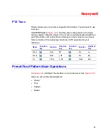
Note
Preset, tour and pattern all need the value to be the
control parameter. You can define it as you require.
You need to refer to your speed dome user’s manual for
the auxiliary function definition. In some cases, it can be
used for special processes.
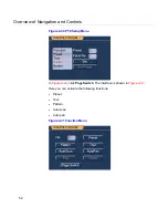
The following setups are usually performed in the
interfaces shown in
Figure 4-29
,
Figure 4-30
and
Figure
4-31
.
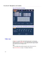
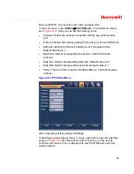
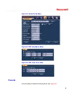
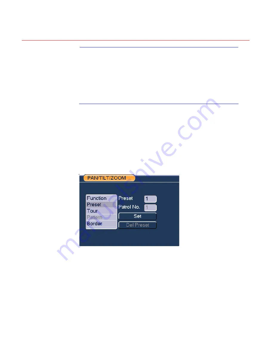
Preset Setup
In
Figure 4-29
, use eight direction arrows to adjust the camera to the proper
position.
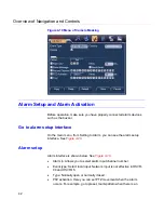
In
Figure 4-30
, click
Preset
and input the preset number. Clicking
Set
will
save the preset.
Now you can add this preset to one tour.
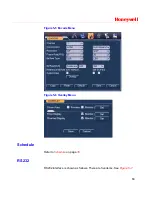
Figure 4-32 Preset Setup
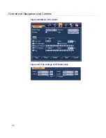
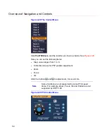
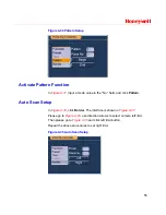
Activate Preset
In
Figure 4-31
, input the preset number in the “No.” field, and click
Preset
.
Содержание HSVR-04
Страница 2: ......
Страница 47: ...Honeywell 39 Figure 4 14 Motion Detection Zone Setting Figure 4 15 PTZ Activation Setting ...
Страница 100: ...Understanding of Menu Operations and Controls 92 Figure 5 38 The Shutdown Menu ...
Страница 103: ...Honeywell 95 Figure 6 2 The Internet Options Window ...
Страница 115: ...Honeywell 107 Figure 6 21 HDD Information Menu Log Here you can view system log See Figure 6 22 ...
Страница 130: ...Web Client Operation 122 Figure 6 37 The NTP Setup Menu Alarm Alarm setup interface is shown as in Figure 6 38 ...
Страница 133: ...Honeywell 125 Figure 6 39 The Detection Setup Menu Figure 6 40 The Detection Zone Setup ...
Страница 142: ...Web Client Operation 134 Figure 6 47 The Auto Maintenance Menu Abnormity The abnormity interface is shown as below ...


