Honeywell
43
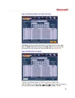
alarm. Click
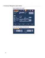
Select
, and you can see an interface as shown in
Figure
4-24
.
Period:
Click
Set
, and you can see an interface as shown in
Figure
4-22
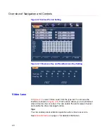
. Here you can set for business days and non-business days. In
Figure 4-25
, click
Set
, and you can see an interface shown in
Figure
4-26
. Here you can set your own setup for business days and non-
business days.
Show message: The system alert you on the local host screen if you
enabled this function.
Send email: The system can send out an email to alert you when an
alarm occurs.
Record channel: You can select the proper channel to record an alarm
video (Multiple choices). At the same time you need to set alarm
recording in the schedule interface (
Main Menu
Setting
Schedule
)
and select the automatic record in manual record interface (
Main
Menu
Advance
Manual Record
).
Alarm output: When the alarm sounds, the system enables the
peripheral alarm devices.
Delay: When the input alarm is completed, the system continues the
alarm output and/or recording for a specified time respectively. The
value ranges from 10-300(Unit: second)
Tour: Here you can enable the tour function when the alarm occurs. It
is a one-window tour; go to
Display
on page
74
for the tour interval
setup.
Note
If there are record channels selected, only the record
channels will be displayed in the tour.
Check boxes to select the corresponding function. After completing all the
settings, click
Save
, and the system goes back to the previous menu.
Содержание HSVR-04
Страница 2: ......
Страница 47: ...Honeywell 39 Figure 4 14 Motion Detection Zone Setting Figure 4 15 PTZ Activation Setting ...
Страница 100: ...Understanding of Menu Operations and Controls 92 Figure 5 38 The Shutdown Menu ...
Страница 103: ...Honeywell 95 Figure 6 2 The Internet Options Window ...
Страница 115: ...Honeywell 107 Figure 6 21 HDD Information Menu Log Here you can view system log See Figure 6 22 ...
Страница 130: ...Web Client Operation 122 Figure 6 37 The NTP Setup Menu Alarm Alarm setup interface is shown as in Figure 6 38 ...
Страница 133: ...Honeywell 125 Figure 6 39 The Detection Setup Menu Figure 6 40 The Detection Zone Setup ...
Страница 142: ...Web Client Operation 134 Figure 6 47 The Auto Maintenance Menu Abnormity The abnormity interface is shown as below ...

