107
NTT 240/460
Operation mode
Installation and user guide
Rev: 4.0
6.16 Closed loop regulation tuning
The tuning procedure is essential to obtain stability and performance of the entire controlled system; the drive, that
performs the control, has PID controller both for the current loop that for the speed loop.
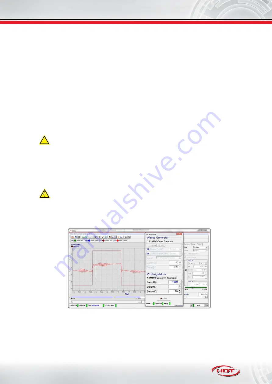
To perform tuning, please use Caliper software and observe some variables with Scope during operation (see
).
The following tuning procedure provides good results in most types of controlled systems, if following conditions
are met:
•
drive must be able to provide motor rated current.
•
load inertia is 6 times grater than motor, maximum.
6.16.1 Current loop tuning
If drive controls an H.D.T. motor, the optimum PID current regulator setting is stored in a motor configuration file,
in the directory to save data in PC used*.
To perform PID current tuning,
it is not essential that the load remains connected to the motor
.
!
If third parts motor is used, it’s recommended to perform motor autophasing
both before and after the PID
current tuning
(see
“6.07 Motor autophasing” pag. 82
). Please use an appropriate mechanical brake, in the
case of vertical axis load (safety condition required during current loop tuning, due to automatic 90° motor
phase autoshifting in order to avoid providing torque.
To perform tuning
, please do the following:
1.
generate a square wave current reference
: use ‘Wave Generator’ function into Caliper software to create
desired reference (see
). Provide to drive a reference with rated motor current
amplitude and period set between 0.05seconds and 0.1seconds.
In this operation, drive provides the rated motor current, so the motor could reach high case temperature.
2.
PID current setting
: parameters to set are K
P
e il K
I
.
•
set K
I
= 1
: integral action erased.
•
increase gradually K
p
until current resonance appears:
in this condition, an evident current resonance
appears in Scope visualization (besides, this condition leads to a motor unusual noise).
•
halve K
P
value
: halving K
P
, system avoids oscillation in transient conditions.
•
increase gradually K
I
: increase until misured current variable accurately follows the desired current
reference. In any case, K
I
parameter should not be greater than
60% of K
P
previously set.
*To get PID current configuration data related to H.D.T. motor, please contact our technical department.
Содержание NTT 240
Страница 129: ......


