


-74-
Model G0841 (Mfd. Since 06/18)
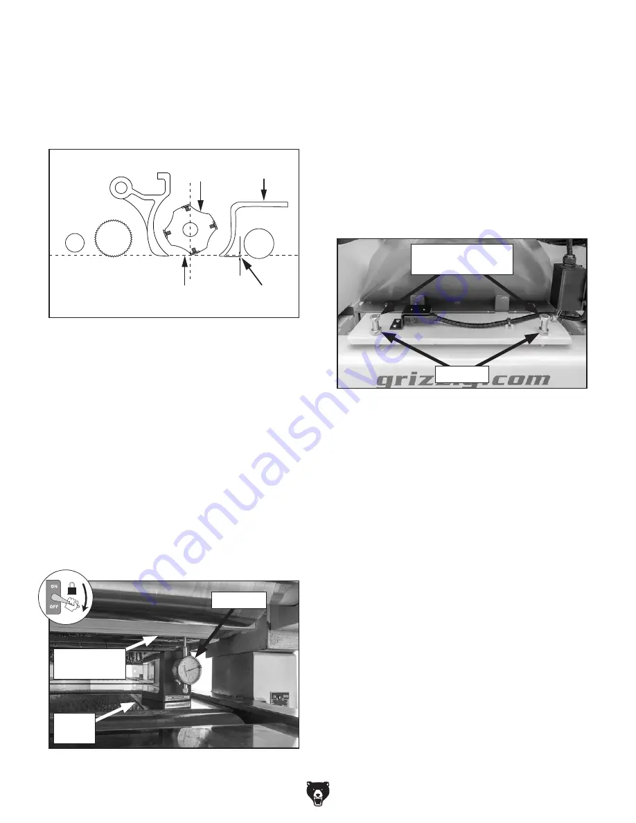
Adjusting Pressure Bar
Upper
Cutterhead
BDC
(Bottom Dead Center)
Pressure
Bar
0.004–0.005"
Figure 119. Correct pressure bar height.
For best thickness planing results, set the pres-
sure bar 0.004–0.005" below BDC, as shown in
Figure 119. Prior to adjusting idler roller, the
headstock must be square to the table. (Refer to
Squaring Headstock on Page 68.)
Item(s) Needed:
Qty
Rotacator or Dial Indicator w/Base .................... 1
Wrench Open-Ends or Socket 19mm................ 2
adjusting pressure bar
To adjust pressure bar height:
1. Set upper cutterhead at BDC. (Refer to
Setting Upper Cutterhead at BDC on
Page 67).
2. DISCONNECT AND LOCK-OUT MACHINE
AT POWER SOURCE!
3. Place Rotacator or dial indicator on planer
table underneath left-side of pressure bar
(see
Figure 120).
Figure 120. Rotacator placed underneath left-
side of pressure bar.
Planer
Table
Rotacator
Bottom of
Pressure Bar
4. Slide Rotacator or dial indicator back and
forth across bottom of pressure bar.
— If pressure bar height is 0.004–0.005"
below BDC, then no height adjustment is
needed. Skip to
Step 7.
— If pressure bar height is not 0.004–0.005"
below BDC, then adjust height of pressure
bar. Proceed to
Step 5.
5. Loosen pressure bar jam nut and height
adjustment bolt (see
Figure 121).
6. Tighten or loosen height adjustment bolt as
needed to set correct pressure bar height,
and then tighten jam nut to secure correct
height setting.
7. Repeat Steps 3–6 on right-side of pressure
bar.
8. If needed, repeat Steps 3–7 until entire pres-
sure bar height is correct.
Figure 121. Location of pressure bar height
adjustment hardware.
Height Adjustment
Bolts
Jam Nuts
Содержание G0841
Страница 84: ......