


Model G0841 (Mfd. Since 06/18)
-69-
1. Set upper cutterhead at BDC. (Refer to
Setting Upper Cutterhead at BDC on
Page 67).
2. DISCONNECT AND LOCK-OUT MACHINE
AT POWER SOURCE!
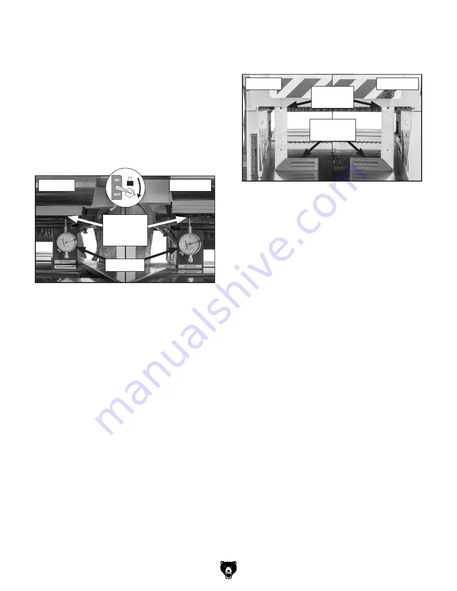
3. Place Rotacator or dial indicator on plan-
er table directly under inserts on leftside
and rightside edge of upper cutterhead (see
Figure 108).
Checking/Squaring Headstock Side-
to-Side
checking squaring headstock side
— If leftside and rightside of headstock are
within 0.050" of one another, then no fur-
ther adjustments are necessary.
— If leftside and rightside of headstock
are not within 0.050" of one another, then
determine which side is higher and pro-
ceed to
Step 7.
7. On side of machine where headstock is
higher, loosen (2) cap screws securing eleva-
tion leadscrew collar (see
Figure 107 on
Page 68).
8. Turn elevation leadscrew collar (see
Figure 107 on Page 68) counterclockwise
until leftside and rightside of headstock are
even, and then tighten (2) cap screws secur-
ing elevation leadscrew collar.
9. Set headstock height. (Refer to Setting
Headstock Height on Page 70.)
— If inserts are at BDC, then proceed to
Step 6.
— If edge inserts are not at BDC, then deter-
mine which side is higher and proceed to
Step 4.
4. On side of machine where headstock is
higher, loosen (2) cap screws securing eleva-
tion leadscrew collar (see
Figure 107 on
Page 68).
5. Turn elevation leadscrew collar (see
Figure 107 on Page 68) counterclockwise
until inserts on leftside and rightside edge
of upper cutterhead are at BDC, and then
tighten (2) cap screws securing elevation
leadscrew collar.
Figure 109. Capenter's square placed under
front edge of headstock.
Figure 108. Rotacator placed under inserts on
edge of upper cutterhead.
Rightside
Leftside
Rotacator
Inserts on
Edge of
Cutterhead
6. Place carpenter's square on rightside and
leftside of infeed table under front edge of
headstock (see
Figure 109).
Rightside
Leftside
Edge of
Headstock
Carpenter's
Square
Содержание G0841
Страница 84: ......