


-42-
Model G0841 (Mfd. Since 06/18)
Rotating/Replacing
Cutterhead Inserts
Items Needed
Qty
Indexable Carbide Inserts ................. As Needed
Torx Screws M6-1 x 12 ...................... As Needed
T-20 Torx Bit ...................................................... 1
Torque Wrench .................................................. 1
Adjustable Wrench ............................................ 1
Air Compressor or Shop Vacuum ...................... 1
Stiff Brush .......................................................... 1
Heavy Leather Gloves ................................1 Pair
T26685 or ISO 32 Equivalent Oil ...... As Needed
Paint Pen (Optional) .......................................... 1
rotating replacing cutterhead inserts
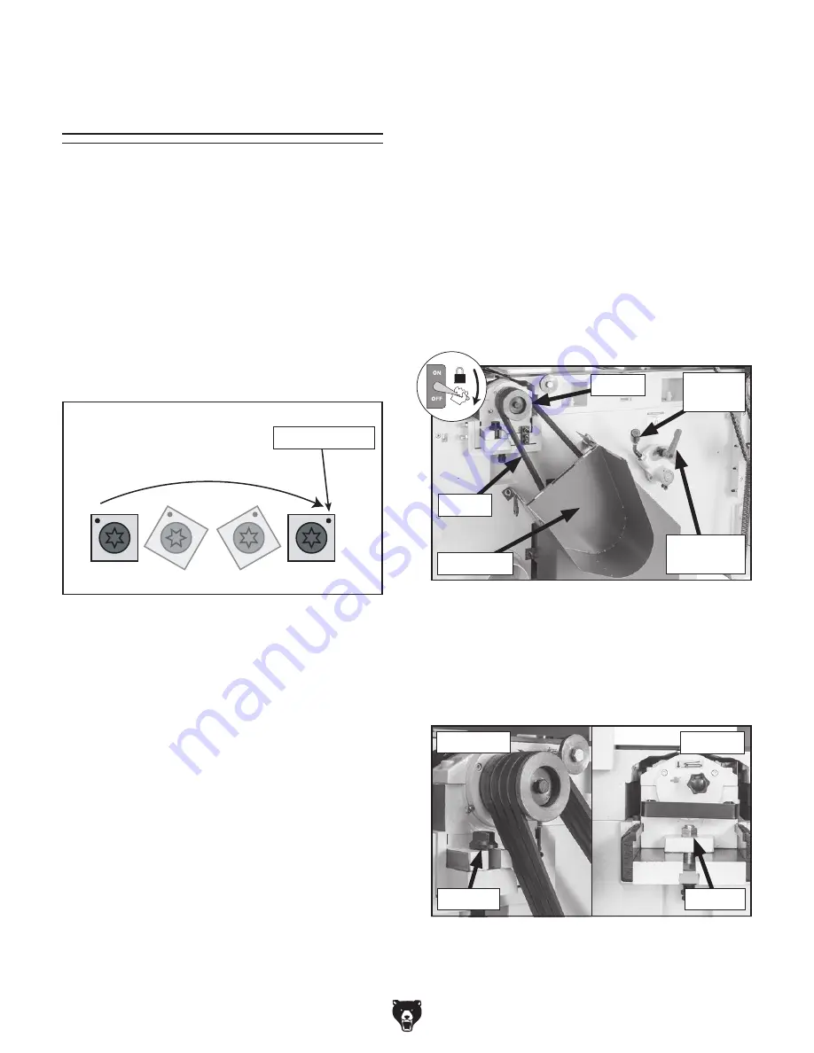
1. DISCONNECT AND LOCK-OUT MACHINE
AT POWER SOURCE!
2. Open chain drive access door and lower
cutterhead belt cover (see
Figure 49).
3. Loosen tension lock lever and pull up on ten-
sion lever until there is slack between V-belts
and lower cutterhead pulley (see
Figure 49).
While pulling tension lever up, tighten tension
lock lever.
Tip: To help ensure each V-belt remains with
its matching pulley, use a paint pen to num-
ber V-belts.
Lower Cutterhead Inserts
Figure 49. Lower cutterhead belt cover opened.
Tension
Lock Lever
Belt Cover
Tension
Lever
V-Belts
Pulley
Figure 50. Location of lower cutterhead hex bolt
and hex nut.
Hex Bolt
Hex Nut
Leftside
Rightside
The spiral cutterhead(s) is equipped with 4-sided
indexable carbide inserts. Each insert can be
rotated and re-installed to use any one of its four
cutting edges. Therefore, if one cutting edge
becomes dull or damaged, simply rotate it 90˚ (as
shown below) to use a sharp cutting edge.
The inserts have a reference dot on one corner.
The position of the reference dot on installed
inserts can be used to track which edges are
sharp/unused and which edges are dull or dam-
aged. Replace inserts once the reference dot has
been rotated back to its original position.
Reference Dot
4. Remove V-belts from lower cutterhead pul-
ley. Leave V-belts on motor pulley.
5. Loosen hex bolt and hex nut (see Figure 50)
that secure lower cutterhead to carriage.
Содержание G0841
Страница 84: ......