GE Multilin
L90 Line Current Differential System
9-33
9 THEORY OF OPERATION
9.4 PHASE DISTANCE APPLIED TO POWER TRANSFORMERS
9
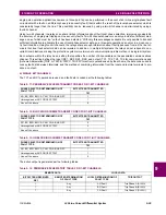
If installed at the location X, the relay would use the following input signals for its phase AB distance element:
V
=
V
AB
= 77.402 kV
57.5° primary or 29.49 V
57.5° secondary
I
=
I
A
–
I
B
= 2.576 kA
–27.6° primary or 42.93 A
–27.6° secondary
And consequently it would see an apparent impedance of:
Z
app
=
V
/
I
= 30.05
85° primary or 0.687
85° secondary
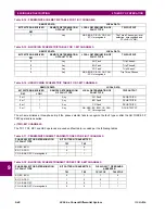
If applied at location H, the relay sees the following input signals:
The relay is set as follows:
XFMR VOL CONNECTION
= “Dy11”
XFMR CUR CONNECTION
= “Dy11”
Consequently, the following signals are applied to the phase AB distance element:
(EQ 9.37)
(EQ 9.38)
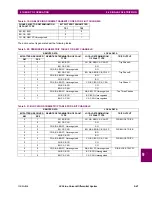
This results in the following apparent impedance:
(EQ 9.39)
The above value is a correct measure of the distance from the VT location to the fault. For relay location 2, this certainly
includes the positive-sequence impedance of the transformer:
(EQ 9.40)
Thus, 0.127
90° + 0.05779
85° = 0.1847
88.4° primary side or 2.569
88.4° on the secondary side.
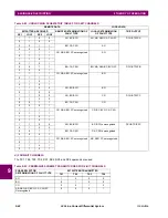
The above example illustrates how the relay maintains correct reach for fault behind power transformers. When installed at
X, the relay shall be set to 0.687
85° secondary in order to reach to the fault shown in the figure. When installed at H,
the relay shall be set to 2.569
88.4° to ensure exactly same coverage.
See Chapter 9: Application of Settings for more information on setting calculations.
INPUT
PRIMARY
SECONDARY
VA
100.4 kV
–7.32°
38.25 V
–7.32°
VB
97.23 kV
–53.4°
37.04 V
–53.4°
VC
181.8 kV
–150.0°
69.26 V
–150.0°
IA
1.288 kA
–27.6°
21.47 A
–27.6°
IB
1.288 kA
152.4°
21.47 A
152.4°
IC
0
0
INPUT
PRIMARY
SECONDARY
VA
7.584 kV
–5.59°
69.95 V
–5.59°
VB
6.269 kV
–120.1°
54.52 V
–120.1°
VC
7.751 kV
125.5°
65.84 V
125.5°
IA
16.976 kA
–27.6°
10.61 A
–27.6°
IB
33.952 kA
152.4°
21.22 A
152.4°
IC
16.976 kA
–27.6°
10.61 A
–27.6°
V
1
3
-------
V
AB
V
BC
10.861 kV 59.9
primary or 94.45 V 59.9
secondary
I
3
I
B
58.860 kA
27.6
primary or 36.75 A
27.6
secondary
Z
app
V
I
----
94.45 kV 59.9
36.75 kA
27.6
----------------------------------------------
2.570
87.5
secondary
Z
T
at 13.8 kV
10
100
----------
13.8 kV
2
150 MVA
----------------------------
0.127
90
Z
L
at 13.8 kV
30.11
13.8
315
-----------
2
0.05779
85
Содержание UR Series L90
Страница 14: ...xiv L90 Line Current Differential System GE Multilin 0 1 BATTERY DISPOSAL 0 BATTERY DISPOSAL 0 ...
Страница 68: ...2 34 L90 Line Current Differential System GE Multilin 2 4 SPECIFICATIONS 2 PRODUCT DESCRIPTION 2 ...
Страница 138: ...4 30 L90 Line Current Differential System GE Multilin 4 3 FACEPLATE INTERFACE 4 HUMAN INTERFACES 4 ...
Страница 604: ...9 58 L90 Line Current Differential System GE Multilin 9 6 FAULT LOCATOR 9 THEORY OF OPERATION 9 ...
Страница 652: ...A 16 L90 Line Current Differential System GE Multilin A 1 PARAMETER LISTS APPENDIX A A ...
Страница 772: ...B 120 L90 Line Current Differential System GE Multilin B 4 MEMORY MAPPING APPENDIX B B ...
Страница 802: ...C 30 L90 Line Current Differential System GE Multilin C 7 LOGICAL NODES APPENDIX C C ...
Страница 812: ...D 10 L90 Line Current Differential System GE Multilin D 1 IEC 60870 5 104 APPENDIX D D ...
Страница 824: ...E 12 L90 Line Current Differential System GE Multilin E 2 DNP POINT LISTS APPENDIX E E ...
Страница 834: ...F 10 L90 Line Current Differential System GE Multilin F 3 WARRANTY APPENDIX F F ...
Страница 846: ...xii L90 Line Current Differential System GE Multilin INDEX ...


