


5-188
L90 Line Current Differential System
GE Multilin
5.6 GROUPED ELEMENTS
5 SETTINGS
5
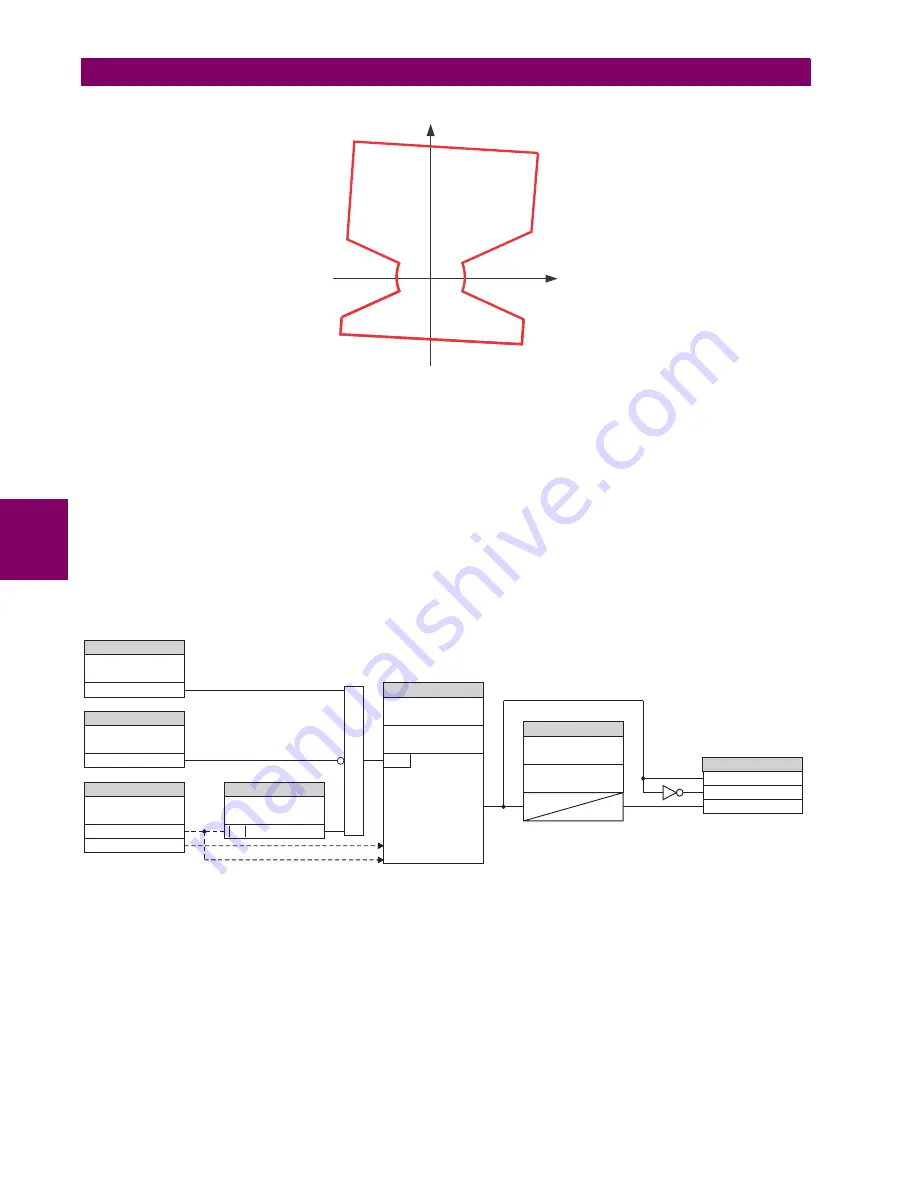
Figure 5–92: LOAD ENCROACHMENT APPLIED TO DISTANCE ELEMENT
•
LOAD ENCROACHMENT MIN VOLT:
This setting specifies the minimum positive-sequence voltage required for oper-
ation of the element. If the voltage is below this threshold a blocking signal will not be asserted by the element. When
selecting this setting one must remember that the L90 measures the phase-to-ground sequence voltages regardless of
the VT connection.
The nominal VT secondary voltage as specified with the
SYSTEM SETUP
AC INPUTS
VOLTAGE BANK X5
PHASE
VT SECONDARY
setting is the per-unit base for this setting.
•
LOAD ENCROACHMENT REACH:
This setting specifies the resistive reach of the element as shown in the
Load
encroachment characteristic
diagram. This setting should be entered in secondary ohms and be calculated as the pos-
itive-sequence resistance seen by the relay under maximum load conditions and unity power factor.
•
LOAD ENCROACHMENT ANGLE:
This setting specifies the size of the blocking region as shown on the
Load
encroachment characteristic
diagram and applies to the positive-sequence impedance.
Figure 5–93: LOAD ENCROACHMENT SCHEME LOGIC
837731A1.CDR
X
R
SETTING
SETTING
SETTING
SETTING
SETTINGS
SETTINGS
FLEXLOGIC OPERANDS
LOAD ENCROACHMENT
FUNCTION:
LOAD ENCRMNT BLK:
LOAD ENCROACHMENT
SOURCE:
LOAD ENCROACHMENT
MIN VOLT:
LOAD ENCROACHMENT
RST DELAY:
LOAD ENCROACHMENT
PKP DELAY:
LOAD ENCROACHMENT
REACH:
LOAD ENCROACHMENT
ANGLE:
Load Encroachment
Characteristic
LOAD ENCHR OP
LOAD ENCHR DPO
LOAD ENCHR PKP
Off=0
Pos Seq Voltage (V_1)
V_1 > Pickup
Pos Seq Current (I_1)
Enabled=1
827847A3.CDR
RUN
t
t
PKP
RST
AND
Содержание UR Series L90
Страница 14: ...xiv L90 Line Current Differential System GE Multilin 0 1 BATTERY DISPOSAL 0 BATTERY DISPOSAL 0 ...
Страница 68: ...2 34 L90 Line Current Differential System GE Multilin 2 4 SPECIFICATIONS 2 PRODUCT DESCRIPTION 2 ...
Страница 138: ...4 30 L90 Line Current Differential System GE Multilin 4 3 FACEPLATE INTERFACE 4 HUMAN INTERFACES 4 ...
Страница 604: ...9 58 L90 Line Current Differential System GE Multilin 9 6 FAULT LOCATOR 9 THEORY OF OPERATION 9 ...
Страница 652: ...A 16 L90 Line Current Differential System GE Multilin A 1 PARAMETER LISTS APPENDIX A A ...
Страница 772: ...B 120 L90 Line Current Differential System GE Multilin B 4 MEMORY MAPPING APPENDIX B B ...
Страница 802: ...C 30 L90 Line Current Differential System GE Multilin C 7 LOGICAL NODES APPENDIX C C ...
Страница 812: ...D 10 L90 Line Current Differential System GE Multilin D 1 IEC 60870 5 104 APPENDIX D D ...
Страница 824: ...E 12 L90 Line Current Differential System GE Multilin E 2 DNP POINT LISTS APPENDIX E E ...
Страница 834: ...F 10 L90 Line Current Differential System GE Multilin F 3 WARRANTY APPENDIX F F ...
Страница 846: ...xii L90 Line Current Differential System GE Multilin INDEX ...


