


GE Multilin
L90 Line Current Differential System
5-63
5 SETTINGS
5.2 PRODUCT SETUP
5
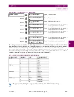
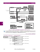
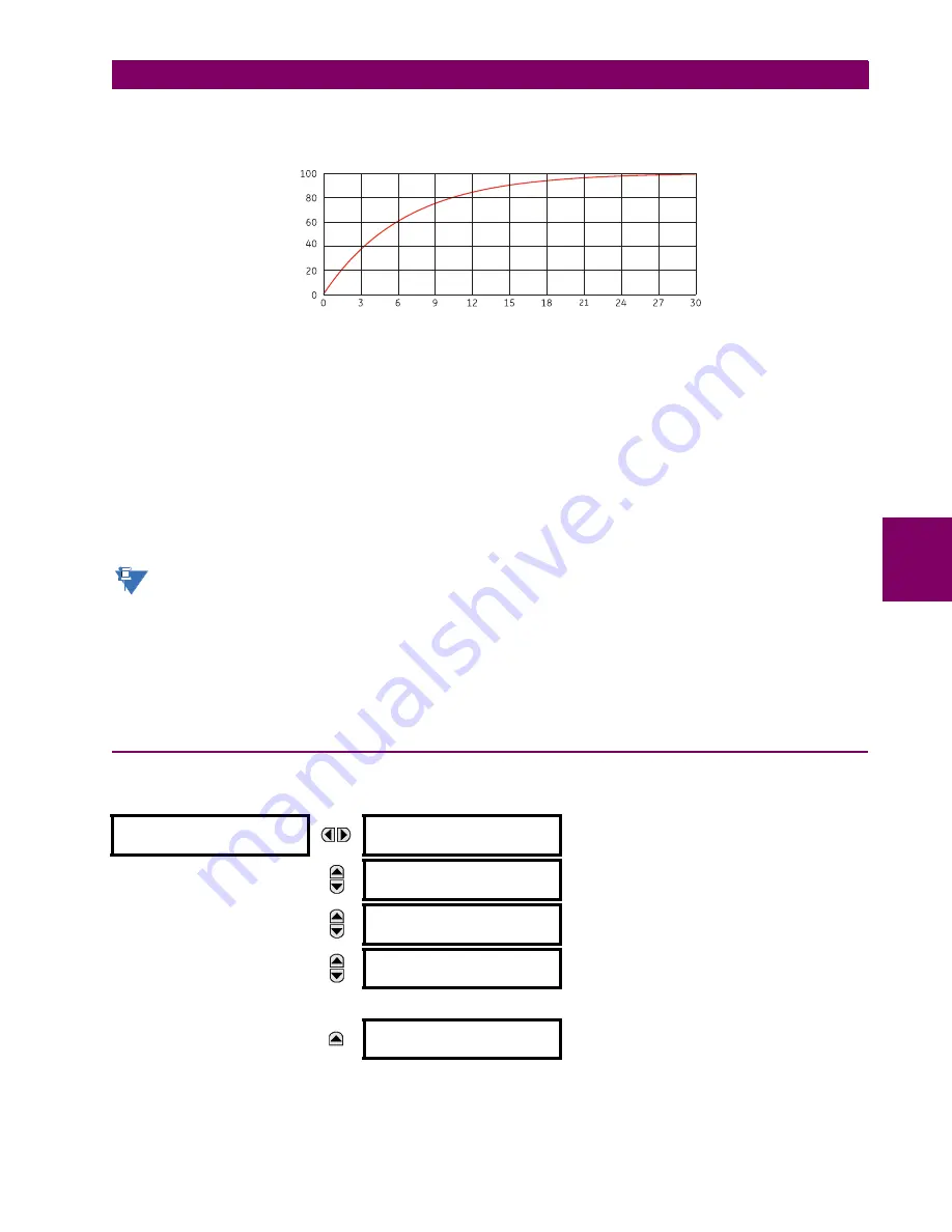
The 90% thermal response time characteristic of 15 minutes is illustrated below. A setpoint establishes the time to reach
90% of a steady-state value, just as the response time of an analog instrument. A steady state value applied for twice the
response time will indicate 99% of the value.
Figure 5–8: THERMAL DEMAND CHARACTERISTIC
CALCULATION METHOD 2: BLOCK INTERVAL
This method calculates a linear average of the quantity (RMS current, real power, reactive power, or apparent power) over
the programmed demand time interval, starting daily at 00:00:00 (i.e. 12:00 am). The 1440 minutes per day is divided into
the number of blocks as set by the programmed time interval. Each new value of demand becomes available at the end of
each time interval.
CALCULATION METHOD 2a: BLOCK INTERVAL (with Start Demand Interval Logic Trigger)
This method calculates a linear average of the quantity (RMS current, real power, reactive power, or apparent power) over
the interval between successive Start Demand Interval logic input pulses. Each new value of demand becomes available at
the end of each pulse. Assign a FlexLogic™ operand to the
DEMAND TRIGGER
setting to program the input for the new
demand interval pulses.
If no trigger is assigned in the
DEMAND TRIGGER
setting and the
CRNT DEMAND METHOD
is "Block Interval", use cal-
culating method #2. If a trigger is assigned, the maximum allowed time between 2 trigger signals is 60 minutes. If
no trigger signal appears within 60 minutes, demand calculations are performed and available and the algorithm
resets and starts the new cycle of calculations. The minimum required time for trigger contact closure is 20
s.
CALCULATION METHOD 3: ROLLING DEMAND
This method calculates a linear average of the quantity (RMS current, real power, reactive power, or apparent power) over
the programmed demand time interval, in the same way as Block Interval. The value is updated every minute and indicates
the demand over the time interval just preceding the time of update.
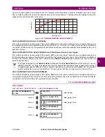
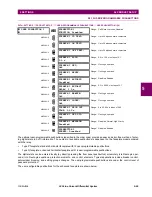
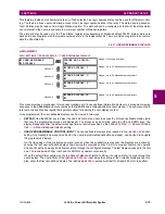
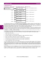
5.2.12 USER-PROGRAMMABLE LEDS
a) MAIN MENU
PATH: SETTINGS
PRODUCT SETUP
USER-PROGRAMMABLE LEDS
USER-PROGRAMMABLE
LEDS
LED TEST
See below
MESSAGE
TRIP & ALARM LEDS
MESSAGE
USER-PROGRAMMABLE
LED1
MESSAGE
USER-PROGRAMMABLE
LED2
MESSAGE
USER-PROGRAMMABLE
LED48
842787A1.CDR
Time (minutes)
Demand
(%)
NOTE
Содержание UR Series L90
Страница 14: ...xiv L90 Line Current Differential System GE Multilin 0 1 BATTERY DISPOSAL 0 BATTERY DISPOSAL 0 ...
Страница 68: ...2 34 L90 Line Current Differential System GE Multilin 2 4 SPECIFICATIONS 2 PRODUCT DESCRIPTION 2 ...
Страница 138: ...4 30 L90 Line Current Differential System GE Multilin 4 3 FACEPLATE INTERFACE 4 HUMAN INTERFACES 4 ...
Страница 604: ...9 58 L90 Line Current Differential System GE Multilin 9 6 FAULT LOCATOR 9 THEORY OF OPERATION 9 ...
Страница 652: ...A 16 L90 Line Current Differential System GE Multilin A 1 PARAMETER LISTS APPENDIX A A ...
Страница 772: ...B 120 L90 Line Current Differential System GE Multilin B 4 MEMORY MAPPING APPENDIX B B ...
Страница 802: ...C 30 L90 Line Current Differential System GE Multilin C 7 LOGICAL NODES APPENDIX C C ...
Страница 812: ...D 10 L90 Line Current Differential System GE Multilin D 1 IEC 60870 5 104 APPENDIX D D ...
Страница 824: ...E 12 L90 Line Current Differential System GE Multilin E 2 DNP POINT LISTS APPENDIX E E ...
Страница 834: ...F 10 L90 Line Current Differential System GE Multilin F 3 WARRANTY APPENDIX F F ...
Страница 846: ...xii L90 Line Current Differential System GE Multilin INDEX ...


