6-10
N60 Network Stability and Synchrophasor Measurement System
GE Multilin
6.3 METERING
6 ACTUAL VALUES
6
b) UR CONVENTION FOR MEASURING PHASE ANGLES
All phasors calculated by UR-series relays and used for protection, control and metering functions are rotating phasors that
maintain the correct phase angle relationships with each other at all times.
For display and oscillography purposes, all phasor angles in a given relay are referred to an AC input channel pre-selected
by the
SETTINGS
ÖØ
SYSTEM SETUP
ÖØ
POWER SYSTEM
ÖØ
FREQUENCY AND PHASE REFERENCE
setting. This setting
defines a particular AC signal source to be used as the reference.
If the AC signal pre-selected by the relay upon configuration is not measurable, the phase angles are not referenced. The
phase angles are assigned as positive in the leading direction, and are presented as negative in the lagging direction, to
more closely align with power system metering conventions. This is illustrated below.
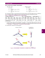
Figure 6–2: UR PHASE ANGLE MEASUREMENT CONVENTION
c) UR CONVENTION FOR MEASURING SYMMETRICAL COMPONENTS
The UR-series of relays calculate voltage symmetrical components for the power system phase A line-to-neutral voltage,
and symmetrical components of the currents for the power system phase A current. Owing to the above definition, phase
angle relations between the symmetrical currents and voltages stay the same irrespective of the connection of instrument
transformers. This is important for setting directional protection elements that use symmetrical voltages.
For display and oscillography purposes the phase angles of symmetrical components are referenced to a common refer-
ence as described in the previous sub-section.
WYE-CONNECTED INSTRUMENT TRANSFORMERS:
The above equations apply to currents as well.
•
ABC phase rotation:
•
ACB phase rotation:
827845A1.CDR
UR phase angle
reference
0
o
-45
o
-90
o
-135
o
-270
o
-225
o
-180
o
-315
o
positive
angle
direction
V_0
1
3
---
V
AG
V
BG
V
CG
+
+
(
)
=
V_1
1
3
---
V
AG
aV
BG
a
2
V
CG
+
+
(
)
=
V_2
1
3
---
V
AG
a
2
V
BG
aV
CG
+
+
(
)
=
V_0
1
3
---
V
AG
V
BG
V
CG
+
+
(
)
=
V_1
1
3
---
V
AG
a
2
V
BG
aV
CG
+
+
(
)
=
V_2
1
3
---
V
AG
aV
BG
a
2
V
CG
+
+
(
)
=
Содержание N60 UR Series
Страница 2: ......
Страница 4: ......
Страница 330: ...6 24 N60 Network Stability and Synchrophasor Measurement System GE Multilin 6 5 PRODUCT INFORMATION 6 ACTUAL VALUES 6 ...
Страница 340: ...7 10 N60 Network Stability and Synchrophasor Measurement System GE Multilin 7 2 TARGETS 7 COMMANDS AND TARGETS 7 ...
Страница 436: ...B 78 N60 Network Stability and Synchrophasor Measurement System GE Multilin B 4 MEMORY MAPPING APPENDIXB B ...
Страница 474: ...D 10 N60 Network Stability and Synchrophasor Measurement System GE Multilin D 1 IEC 60870 5 104 PROTOCOL APPENDIXD D ...
Страница 486: ...E 12 N60 Network Stability and Synchrophasor Measurement System GE Multilin E 2 DNP POINT LISTS APPENDIXE E ...


