


5-94
N60 Network Stability and Synchrophasor Measurement System
GE Multilin
5.4 FLEXLOGIC™
5 SETTINGS
5
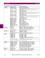
ELEMENT:
Phase undervoltage
PHASE UV1 PKP
PHASE UV1 OP
PHASE UV1 DPO
PHASE UV1 PKP A
PHASE UV1 PKP B
PHASE UV1 PKP C
PHASE UV1 OP A
PHASE UV1 OP B
PHASE UV1 OP C
PHASE UV1 DPO A
PHASE UV1 DPO B
PHASE UV1 DPO C
At least one phase of phase undervoltage 1 has picked up
At least one phase of phase undervoltage 1 has operated
At least one phase of phase undervoltage 1 has dropped out
Phase A of phase undervoltage 1 has picked up
Phase B of phase undervoltage 1 has picked up
Phase C of phase undervoltage 1 has picked up
Phase A of phase undervoltage 1 has operated
Phase B of phase undervoltage 1 has operated
Phase C of phase undervoltage 1 has operated
Phase A of phase undervoltage 1 has dropped out
Phase B of phase undervoltage 1 has dropped out
Phase C of phase undervoltage 1 has dropped out
PHASE UV2
Same set of operands as shown for PHASE UV1
ELEMENT:
Synchrophasor
phasor
measurement unit
(PMU)
PMU 1 CURR TRIGGER
PMU 1 FREQ TRIGGER
PMU 1 POWER TRIGGER
PMU 1 ROCOF TRIGGER
PMU 1 VOLT TRIGGER
PMU 1 TRIGGERED
Overcurrent trigger of phasor measurement unit 1 has operated
Abnormal frequency trigger of phasor measurement unit 1 has operated
Overpower trigger of phasor measurement unit 1 has operated
Rate of change of frequency trigger of phasor measurement unit 1 has
operated
Abnormal voltage trigger of phasor measurement unit 1 has operated
Phasor measurement unit 1 triggered; no events or targets are generated by
this operand
PMU 2 to 4
Same set of operands as shown for PMU 1
ELEMENT:
Synchrophasor one-
shot
PMU ONE-SHOT EXPIRED
PMU ONE-SHOT OP
PMU ONE-SHOT PENDING
Indicates the one-shot operation has been executed, and the present time is
at least 30 seconds past the scheduled one-shot time
Indicates the one-shot operation is pending; that is, the present time is before
the scheduled one-shot time
Indicates the one-shot operation and remains asserted for 30 seconds
afterwards
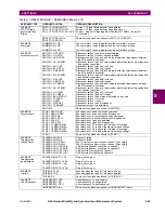
ELEMENT:
Power swing detect
POWER SWING OUTER
POWER SWING MIDDLE
POWER SWING INNER
POWER SWING BLOCK
POWER SWING TMR1 PKP
POWER SWING TMR2 PKP
POWER SWING TMR3 PKP
POWER SWING TMR4 PKP
POWER SWING TRIP
POWER SWING 50DD
POWER SWING INCOMING
POWER SWING OUTGOING
POWER SWING UN/BLOCK
Positive-sequence impedance in outer characteristic
Positive-sequence impedance in middle characteristic
Positive-sequence impedance in inner characteristic
Power swing blocking element operated
Power swing timer 1 picked up
Power swing timer 2 picked up
Power swing timer 3 picked up
Power swing timer 4 picked up
Out-of-step tripping operated
The power swing element detected a disturbance other than power swing
An unstable power swing has been detected (incoming locus)
An unstable power swing has been detected (outgoing locus)
Asserted when a fault occurs after the power swing blocking condition has
been established
ELEMENT:
Selector switch
SELECTOR 1 POS Y
SELECTOR 1 BIT 0
SELECTOR 1 BIT 1
SELECTOR 1 BIT 2
SELECTOR 1 STP ALARM
SELECTOR 1 BIT ALARM
SELECTOR 1 ALARM
SELECTOR 1 PWR ALARM
Selector switch 1 is in Position Y (mutually exclusive operands)
First bit of the 3-bit word encoding position of selector 1
Second bit of the 3-bit word encoding position of selector 1
Third bit of the 3-bit word encoding position of selector 1
Position of selector 1 has been pre-selected with the stepping up control
input but not acknowledged
Position of selector 1 has been pre-selected with the 3-bit control input but
not acknowledged
Position of selector 1 has been pre-selected but not acknowledged
Position of selector switch 1 is undetermined or restored from memory when
the relay powers up and synchronizes to the three-bit input
SELECTOR 2
Same set of operands as shown above for SELECTOR 1
ELEMENT:
Setting group
SETTING GROUP ACT 1
SETTING GROUP ACT 2
SETTING GROUP ACT 3
SETTING GROUP ACT 4
SETTING GROUP ACT 5
SETTING GROUP ACT 6
Setting group 1 is active
Setting group 2 is active
Setting group 3 is active
Setting group 4 is active
Setting group 5 is active
Setting group 6 is active
ELEMENT:
Disturbance
detector
SRC1 50DD OP
SRC2 50DD OP
SRC3 50DD OP
SRC4 50DD OP
SRC5 50DD OP
SRC6 50DD OP
Source 1 disturbance detector has operated
Source 2 disturbance detector has operated
Source 3 disturbance detector has operated
Source 4 disturbance detector has operated
Source 5 disturbance detector has operated
Source 6 disturbance detector has operated
Table 5–7: N60 FLEXLOGIC™ OPERANDS (Sheet 4 of 7)
OPERAND TYPE
OPERAND SYNTAX
OPERAND DESCRIPTION
Содержание N60 UR Series
Страница 2: ......
Страница 4: ......
Страница 330: ...6 24 N60 Network Stability and Synchrophasor Measurement System GE Multilin 6 5 PRODUCT INFORMATION 6 ACTUAL VALUES 6 ...
Страница 340: ...7 10 N60 Network Stability and Synchrophasor Measurement System GE Multilin 7 2 TARGETS 7 COMMANDS AND TARGETS 7 ...
Страница 436: ...B 78 N60 Network Stability and Synchrophasor Measurement System GE Multilin B 4 MEMORY MAPPING APPENDIXB B ...
Страница 474: ...D 10 N60 Network Stability and Synchrophasor Measurement System GE Multilin D 1 IEC 60870 5 104 PROTOCOL APPENDIXD D ...
Страница 486: ...E 12 N60 Network Stability and Synchrophasor Measurement System GE Multilin E 2 DNP POINT LISTS APPENDIXE E ...