


5-96
N60 Network Stability and Synchrophasor Measurement System
GE Multilin
5.4 FLEXLOGIC™
5 SETTINGS
5
FIXED OPERANDS
Off
Logic = 0. Does nothing and may be used as a delimiter in an equation list;
used as ‘Disable’ by other features.
On
Logic = 1. Can be used as a test setting.
INPUTS/OUTPUTS:
Contact inputs
Cont Ip 1
On
Cont Ip 2
On
↓
Cont Ip 1
Off
Cont Ip 2
Off
↓
(will not appear unless ordered)
(will not appear unless ordered)
↓
(will not appear unless ordered)
(will not appear unless ordered)
↓
INPUTS/OUTPUTS:
Contact outputs,
current
(from detector on
form-A output only)
Cont Op 1
IOn
Cont Op 2
IOn
↓
(will not appear unless ordered)
(will not appear unless ordered)
↓
Cont Op 1
IOff
Cont Op 2
IOff
↓
(will not appear unless ordered)
(will not appear unless ordered)
↓
INPUTS/OUTPUTS:
Contact outputs,
voltage
(from detector on
form-A output only)
Cont Op 1
VOn
Cont Op 2
VOn
↓
(will not appear unless ordered)
(will not appear unless ordered)
↓
Cont Op 1
VOff
Cont Op 2
VOff
↓
(will not appear unless ordered)
(will not appear unless ordered)
↓
INPUTS/OUTPUTS:
Direct analog inputs
DIR ANA 1 DEADBAND
DIR ANA 1 FORCE
DIR ANA 1 INTEGRITY
A deadband has triggered direct analog input 1
A user force operand has triggered direct analog input 1
An integrity timeout has triggered direct analog input 1
DIR ANA 2 to DIRECT ANA 32
Same set of operands as per DIRECT ANA 1 above
INPUTS/OUTPUTS
Direct inputs
DIRECT INPUT 1 On
↓
DIRECT INPUT 64 On
Flag is set, logic=1
↓
Flag is set, logic=1
INPUTS/OUTPUTS:
Remote inputs
REMOTE INPUT 1 On
↓
REMOTE INPUT 32 On
Flag is set, logic=1
↓
Flag is set, logic=1
INPUTS/OUTPUTS:
Virtual inputs
Virt Ip 1
On
↓
Virt Ip 64
On
Flag is set, logic=1
↓
Flag is set, logic=1
INPUTS/OUTPUTS:
Virtual outputs
Virt Op 1
On
↓
Virt Op 96
On
Flag is set, logic=1
↓
Flag is set, logic=1
LED INDICATORS:
Fixed front panel
LEDs
LED IN SERVICE
LED TROUBLE
LED TEST MODE
LED TRIP
LED ALARM
LED PICKUP
LED VOLTAGE
LED CURRENT
LED FREQUENCY
LED OTHER
LED PHASE A
LED PHASE B
LED PHASE C
LED NEUTRAL/GROUND
Asserted when the front panel IN SERVICE LED is on.
Asserted when the front panel TROUBLE LED is on.
Asserted when the front panel TEST MODE LED is on.
Asserted when the front panel TRIP LED is on.
Asserted when the front panel ALARM LED is on.
Asserted when the front panel PICKUP LED is on.
Asserted when the front panel VOLTAGE LED is on.
Asserted when the front panel CURRENT LED is on.
Asserted when the front panel FREQUENCY LED is on.
Asserted when the front panel OTHER LED is on.
Asserted when the front panel PHASE A LED is on.
Asserted when the front panel PHASE B LED is on.
Asserted when the front panel PHASE C LED is on.
Asserted when the front panel NEUTRAL/GROUND LED is on.
LED INDICATORS:
LED test
LED TEST IN PROGRESS
An LED test has been initiated and has not finished.
LED INDICATORS:
User-programmable
LEDs
LED USER 1
Asserted when user-programmable LED 1 is on.
LED USER 2 to 48
The operand above is available for user-programmable LEDs 2 through 48.
REMOTE DEVICES
REMOTE DEVICE 1 On
↓
REMOTE DEVICE 16 On
Flag is set, logic=1
↓
Flag is set, logic=1
REMOTE DEVICE 1 Off
↓
REMOTE DEVICE 16 Off
Flag is set, logic=1
↓
Flag is set, logic=1
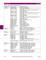
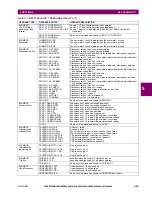
Table 5–7: N60 FLEXLOGIC™ OPERANDS (Sheet 6 of 7)
OPERAND TYPE
OPERAND SYNTAX
OPERAND DESCRIPTION
Содержание N60 UR Series
Страница 2: ......
Страница 4: ......
Страница 330: ...6 24 N60 Network Stability and Synchrophasor Measurement System GE Multilin 6 5 PRODUCT INFORMATION 6 ACTUAL VALUES 6 ...
Страница 340: ...7 10 N60 Network Stability and Synchrophasor Measurement System GE Multilin 7 2 TARGETS 7 COMMANDS AND TARGETS 7 ...
Страница 436: ...B 78 N60 Network Stability and Synchrophasor Measurement System GE Multilin B 4 MEMORY MAPPING APPENDIXB B ...
Страница 474: ...D 10 N60 Network Stability and Synchrophasor Measurement System GE Multilin D 1 IEC 60870 5 104 PROTOCOL APPENDIXD D ...
Страница 486: ...E 12 N60 Network Stability and Synchrophasor Measurement System GE Multilin E 2 DNP POINT LISTS APPENDIXE E ...