GE Multilin
N60 Network Stability and Synchrophasor Measurement System
5-159
5 SETTINGS
5.6 CONTROL ELEMENTS
5
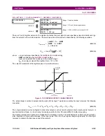
Figure 5–75: 8-BIT COMPARATOR LOGIC
APPLICATION EXAMPLE:
A three-phase active power measured via SRC 1 on the UR-1 IED is to be sent to a remote location UR-2 via the direct
inputs/outputs feature. Upon reception the remote power is to be added to a three phase active power measured locally by
the UR-2 IED via SRC 4. The application should work accurately under an overload of 25% and a power factor of 1.0 at
either location.
An alarm should be established at the UR-2 location if the total power is above 2500 MW for 50 ms. The alarm should be
cleared if the power is below 2000 MW for 1 second.
The following settings and conditions are given.
•
UR-1: Nominal system voltage = 345 kV, SRC 1 CT ratio = 2000:5, Normal load current = 1.8 kA.
•
UR-2: Nominal system voltage = 220 kV, SRC 4 CT ratio = 3000:5, Normal load current = 2.5 kA.
The application requires the following features:
For UR-1:
Digitizer to prepare the measured power for sending to the UR-2 IED, and
direct outputs to send the digitized power to the UR-2 IED.
842014A4.CDR
8BIT COMP 1 BLOCK:
8BIT COMP 1 INPUT MODE:
8BIT COMP 1 DIRECTION:
8BIT COMP 1 PICKUP:
8BIT COMP 1 HYSTERESIS:
8BIT COMP 1 SCALE FACTOR:
8BIT COMP 1 ARG A0:
8BIT COMP 1 PICKUP
DELAY:
8BIT COMP 1 RESET
DELAY:
8BIT COMP 1 ARG B0:
8BIT COMP 1 ADD/SUB:
8BIT COMP 1 ARG A6:
8BIT COMP 1 ARG B6:
8BIT COMP 1 ARG A7:
8BIT COMP 1 ARG B7:
scaling factor
scaling factor
scaling factor
COMP
ARE
SUM
-1
A
-B
Off
On
+B
0.5
SETTING
SETTINGS
SETTINGS
SETTINGS
SETTING
SETTINGS
FLEXLOGIC OPERANDS
FLEXLOGIC OPERANDS
ACTUAL VALUE
ACTUAL VALUE
ACTUAL VALUE
Off=0
BLOCK (see description)
Off=0
Off=0
Off=0
Off=0
Off=0
Off=0
Off=0
...
...
8BIT COMP 1 OP
8BIT COMP 1 BIT 0
8BIT COMP 1 BIT 2
8BIT COMP 1 BIT 4
8BIT COMP 1 BIT 6
8BIT COMP 1 A
8BIT COMP 1 Out
8BIT COMP 1 B
8BIT COMP 1 DPO
8BIT COMP 1 PKP
8BIT COMP 1 BIT 1
8BIT COMP 1 BIT 3
8BIT COMP 1 BIT 5
8BIT COMP 1 BIT 7
t
PKP
t
RST
Содержание N60 UR Series
Страница 2: ......
Страница 4: ......
Страница 330: ...6 24 N60 Network Stability and Synchrophasor Measurement System GE Multilin 6 5 PRODUCT INFORMATION 6 ACTUAL VALUES 6 ...
Страница 340: ...7 10 N60 Network Stability and Synchrophasor Measurement System GE Multilin 7 2 TARGETS 7 COMMANDS AND TARGETS 7 ...
Страница 436: ...B 78 N60 Network Stability and Synchrophasor Measurement System GE Multilin B 4 MEMORY MAPPING APPENDIXB B ...
Страница 474: ...D 10 N60 Network Stability and Synchrophasor Measurement System GE Multilin D 1 IEC 60870 5 104 PROTOCOL APPENDIXD D ...
Страница 486: ...E 12 N60 Network Stability and Synchrophasor Measurement System GE Multilin E 2 DNP POINT LISTS APPENDIXE E ...


