


GE Power Management
469 Motor Management Relay
4-35
4 SETPOINT PROGRAMMING
4.6 S5 THERMAL MODEL
4
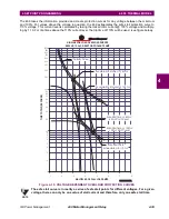
c) VOLTAGE DEPENDENT OVERLOAD CURVE
If the motor is called upon to drive a high inertia load, it is quite possible and acceptable that the acceleration
time exceeds the safe stall time (bearing in mind that a locked rotor condition is quite different than an acceler-
ation condition). In this instance, each distinct portion of the thermal limit curve must be known and protection
must be coordinated against that curve. The relay that is protecting the motor must be able to distinguish
between a locked rotor condition, an accelerating condition and a running condition. The 469 Voltage Depen-
dent Overload Curve feature is tailored to protect these types of motors. Voltage is continually monitored dur-
ing motor starting and the acceleration thermal limit curve is adjusted accordingly.
The Voltage Dependent Overload Curve is comprised of the three characteristic shapes of thermal limit curves
as determined by the stall or locked rotor condition, acceleration, and running overload. The curve is con-
structed by entering a custom curve shape for the running overload protection curve. Next, a point must be
entered for the acceleration protection curve at the point of intersection with the custom curve, based on the
minimum allowable starting voltage as defined by the minimum allowable line voltage. The locked rotor current
and safe stall time must also be entered for that voltage. A second point of intersection must be entered for
100% line voltage. Once again, the locked rotor current and the safe stall time must be entered, this time for
100% line voltage. The protection curve created from the safe stall time and intersection point will be dynamic
based on the measured line voltage between the minimum allowable line voltage and the 100% line voltage.
This method of protection inherently accounts for the change in motor speed as an impedance relay would.
The change in impedance is reflected by motor terminal voltage and line current. For any given speed at any
given line voltage, there is only one value of line current.
EXAMPLE:
To illustrate the Voltage Dependent Overload Curve feature, the thermal limits of Figure 4–10: THERMAL LIM-
ITS FOR HIGH INERTIAL LOAD will be used.
1.
Construct a custom curve for the running overload thermal limit. If the curve does not extend to the accel-
eration thermal limits, extend it such that the curve intersects the acceleration thermal limit curves (see
Figure 4–11: VOLTAGE DEPENDENT OVERLOAD (CUSTOM CURVE) on page 4–37).
2.
Enter the per unit current value for the acceleration overload curve intersect with the custom curve for 80%
line voltage. Also enter the per unit current and safe stall protection time for 80% line voltage (see Figure
4–12: VOLTAGE DEPENDENT OVERLOAD (ACCELERATION CURVES) on page 4–38).
3.
Enter the per unit current value for the acceleration overload curve intersect with the custom curve for
100% line voltage. Also enter the per unit current and safe stall protection time for 100% line voltage (see
Figure 4–12: VOLTAGE DEPENDENT OVERLOAD (ACCELERATION CURVES) on page 4–38).
Содержание MOTOR MANAGEMENT RELAY 469
Страница 2: ......
Страница 4: ......
Страница 12: ......
Страница 22: ......
Страница 50: ......
Страница 142: ......
Страница 240: ......
Страница 254: ......
Страница 272: ......
Страница 286: ......
Страница 290: ......
Страница 294: ......
Страница 298: ......
Страница 300: ......
Страница 302: ......


