5-274
L30 LINE CURRENT DIFFERENTIAL SYSTEM – INSTRUCTION MANUAL
CONTROL ELEMENTS
CHAPTER 5: SETTINGS
5
SYNCHK1 MAX VOLT DIFF
— Selects the maximum primary voltage difference in volts between the two sources. A primary
voltage magnitude difference between the two input voltages below this value is within the permissible limit for
synchronism.
SYNCHK1 MAX ANGLE DIFF
— Selects the maximum angular difference in degrees between the two sources. An angular
difference between the two input voltage phasors below this value is within the permissible limit for synchronism.
SYNCHK1 MAX FREQ HYSTERESIS
— Specifies the required hysteresis for the maximum frequency difference condition. The
condition becomes satisfied when the frequency difference becomes lower than
SYNCHK1 MAX FREQ DIFF
. Once the
Synchrocheck element has operated, the frequency difference must increase above the
SYNCHK1 MAX FREQ DIFF + SYNCHK1
MAX FREQ HYSTERESIS
sum to drop out (assuming the other two conditions, voltage and angle, remain satisfied).
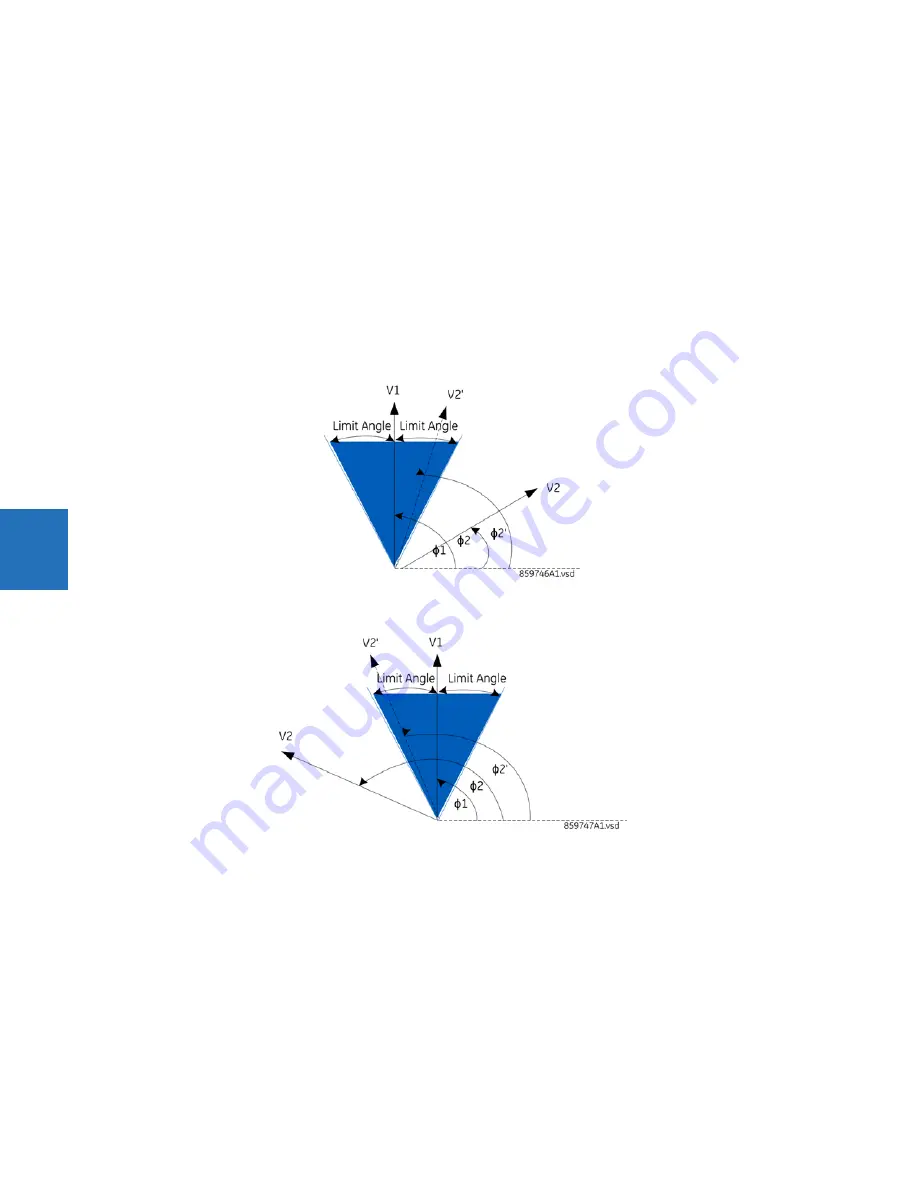
SYNCHK1 SYNC CLOSE
— Enables the dynamic mode of synchrocheck. When it is enabled, the location of where the present
V2 vector will be arriving to synchronize (shown as V2' in the figures here) with breaker close time being taken into account
will be predicted based on the measured slip frequency so that breaker close command can be issued in advance to
ensure the synchronism at the time when the breaker is actually closed.
Figure 5-144: Synchrocheck plot for slip > 0 (slip = F2-F1)
Figure 5-145: Synchrocheck plot for slip < 0 (slip = F2-F1)
SYNCHK1 S-CLS MAX dF
— Specifies the maximum slip frequency allowed in Hz in the dynamic mode. The dynamic mode is
disarmed when the slip frequency exceeds this setting.
SYNCHK1 S-CLS MIN dF
— Specifies the minimum slip frequency allowed in Hz in the dynamic mode. The dynamic mode is
disarmed when the slip frequency drops below this setting.
SYNCHK1 S-CLS BRK TIME
— Specifies the breaker closing time in seconds.
SYNCHK1 V2 MAG CORR FACTOR
— Specifies the magnitude correction factor of source V2. This setting is used for V2
magnitude compensation so that V2 magnitude can be directly compared with V1 magnitude. For example, when V1 and
V2 are taken from 2 different windings of the transformer and at different voltage levels, the magnitude compensation
must be performed before starting magnitude comparison in synchrocheck element.
Содержание L30
Страница 10: ...x L30 LINE CURRENT DIFFERENTIAL SYSTEM INSTRUCTION MANUAL TABLE OF CONTENTS ...
Страница 14: ...1 4 L30 LINE CURRENT DIFFERENTIAL SYSTEM INSTRUCTION MANUAL FOR FURTHER ASSISTANCE CHAPTER 1 INTRODUCTION 1 ...
Страница 126: ...3 68 L30 LINE CURRENT DIFFERENTIAL SYSTEM INSTRUCTION MANUAL CONNECT TO D400 GATEWAY CHAPTER 3 INSTALLATION 3 ...
Страница 214: ...4 88 L30 LINE CURRENT DIFFERENTIAL SYSTEM INSTRUCTION MANUAL FLEXLOGIC DESIGN USING ENGINEER CHAPTER 4 INTERFACES 4 ...
Страница 582: ...7 16 L30 LINE CURRENT DIFFERENTIAL SYSTEM INSTRUCTION MANUAL TARGETS MENU CHAPTER 7 COMMANDS AND TARGETS 7 ...
Страница 598: ...9 6 L30 LINE CURRENT DIFFERENTIAL SYSTEM INSTRUCTION MANUAL TESTING CHAPTER 9 COMMISSIONING 9 ...
Страница 622: ...10 24 L30 LINE CURRENT DIFFERENTIAL SYSTEM INSTRUCTION MANUAL FAULT LOCATOR CHAPTER 10 THEORY OF OPERATION 10 ...
Страница 670: ...A 18 L30 LINE CURRENT DIFFERENTIAL SYSTEM INSTRUCTION MANUAL FLEXANALOG ITEMS APPENDIX A FLEXANALOG OPERANDS A ...
Страница 678: ...C 6 L30 LINE CURRENT DIFFERENTIAL SYSTEM INSTRUCTION MANUAL COMMAND LINE INTERFACE APPENDIX C COMMAND LINE INTERFACE C ...
Страница 682: ...D 4 L30 LINE CURRENT DIFFERENTIAL SYSTEM INSTRUCTION MANUAL REVISION HISTORY APPENDIX D MISCELLANEOUS D ...
Страница 686: ...iv L30 LINE CURRENT DIFFERENTIAL SYSTEM INSTRUCTION MANUAL ABBREVIATIONS ...


