GE Power Management
ALPS Advanced Line Protection System
2-21
2 CALCULATION OF SETTINGS
2.3 PROTECTION SETTINGS
2
1.
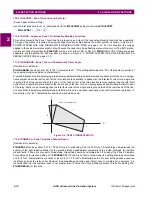
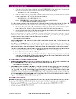
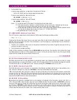
If the reach of the Zone 2 ground distance functions (Z2GRDREACH) at the remote end of the line is less
than twice the positive-sequence impedance of the line, then the proposed setting is:
Z4GRDREACH = 0.85 x Z2GRDREACH
R
2.
If the reach of the Zone 2 ground distance functions at the remote end is greater than twice the positive-
sequence impedance of the line, then the proposed settings are:
Z4GRDREACH = 1.7 x Z2GRDREACH
R
–
Z
1
L
where
Z2GRDREACH
R
= reach of phase Zone 2 functions at remote line terminal
Z
1
L
= positive sequence impedance of protected line
With these proposed settings, proper coordination will be obtained between the tripping and blocking functions at the
remote terminal of the line. It may be possible to use a shorter setting or a longer setting than proposed, but
1.
If a longer setting is used, then the reach should be checked per the maximum allowable reach procedure
given in Section 2.3.2: ZONE 2, ZONE 3, AND ZONE 4 DISTANCE FUNCTIONS on page 2–13.
2.
If a shorter reach setting is used, then the reach should be checked to assure that the function will operate for
all faults that the remote Zone 2 function can operate for.
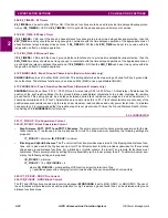
When series capacitors are used on the protected line or in lines adjacent to the protected line, set the Zone 4 ground
distance functions with a reach that is equal to or greater than the reach of the ground distance pilot tripping functions
(normally Zone 2) at the remote end of the transmission line. For example:
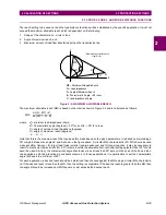
Z4GRDREACH
≥
Z2GRDREACH
R
where
Z2GRDREACH
R
is the reach of the ground distance pilot tripping functions (Zone 2 in this example) at the
remote end of the line.
•
Step Distance and POTT1 Schemes: In all other schemes, the Zone 4 ground distance functions can be used to pro-
vide an additional zone of time delayed backup protection. They can provide a fourth zone of protection in a straight
step distance scheme, or they can be reversed in direction to provide the so-called reversed third zone of protection.
The Zone 4 ground distance functions should be set with a reach commensurate to the application, considering under-
reach caused by intermediate fault current sources. Z4GRDREACH should never be set so large as to:
1.
Exceed the maximum allowable reach (
MR), or
2.
Cause loss of selectivity with any ground distance functions providing time delayed backup on any adjoining
line section. If this requirement cannot be met by limiting the reach, then it may be necessary to get this selec-
tivity by setting timer Z4G_TIME with additional time delay.
407: Z4GCHARANG - Z4 Ground Characteristic Angle
•
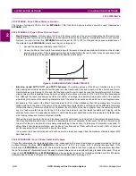
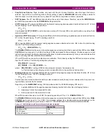
Blocking and Hybrid Schemes: Set the Zone 4 characteristic angle setting to 10° less than the characteristic angle
setting (Z2GCHARANG
R
) of the Zone 2 functions at the remote terminal of the line; that is:
Z4CHARANG = Z2CHARANG
R
– 10°
•
Step Distance, POTT1, and POTT2 Schemes: This setting determines the characteristic shape and, consequently,
the area of resistance coverage provided by the Zone 4 phase distance functions. Z4PCHARANG can be set to 80° to
155° in 5° steps. A 90° setting is recommended; values lower than 90° should not be used except in blocking, hybrid
and POTT2 schemes. If the desired reach, Z4GRDREACH, with a 90° characteristic and with maximum load flow does
not allow the maximum allowable reach criteria to be met, then a "lens-shaped" characteristic must be used. The set-
tings of Z4GRDREACH and Z4GCHARANG may be evaluated by using the formula associated with the method of
Figure 2–5: MAXIMUM ALLOWABLE REACH on page 2–13.
408: Z4DIRECTN - Z4 Direction
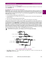
Z4DIRECTN determines the direction of the principle reach of the Zone 4 phase and ground distance functions. The direc-
tion can be set to FORWRD or REVERS with the direction to be used dictated by the particular scheme/application.
•
Blocking, Hybrid, POTT2 Schemes, and Reversed Third Zone Applications: Z4DIRECTN = REVERS
•
All other schemes: Z4DIRECTN = FORWRD
Содержание ALPS
Страница 2: ......
Страница 4: ......
Страница 182: ...5 20 ALPS Advanced Line Protection System GE Power Management 5 5 MOB TESTING 5 FUNCTIONAL TESTS FACTORY SETTINGS 5 ...
Страница 200: ...6 18 ALPS Advanced Line Protection System GE Power Management 6 5 ZONE REACH TESTS 6 FUNCTIONAL TESTS USER SETTINGS 6 ...
Страница 346: ...D 4 ALPS Advanced Line Protection System GE Power Management D 1 KEYPAD MENUS APPENDIXD D ...
Страница 352: ...F 2 ALPS Advanced Line Protection System GE Power Management F 1 WARRANTY INFORMATION APPENDIXF F ...
Страница 366: ...xiv ALPS Advanced Line Protection System GE Power Management INDEX INDEX ...


