GE Power Management
ALPS Advanced Line Protection System
2-41
2 CALCULATION OF SETTINGS
2.3 PROTECTION SETTINGS
2
1709: TLOS1PU - Coordinating Timer 1 Pickup
1710: TLOS1DO - Coordinating Timer 1 Dropout
1711: TLOS2PU - Coordinating Timer 2 Pickup
1712: TLOS3PU - Coordinating Timer 3 Pickup
1713: TLOS4PU - Coordinating Timer 4 Pickup
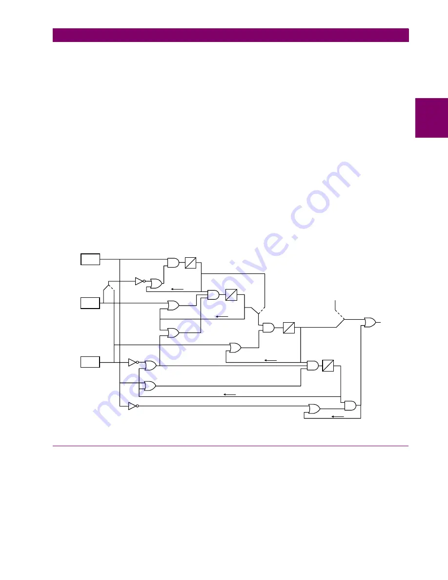
These five settings are related to each other with the object being to detect the fastest possible swing and to produce an
OST output in a secure manner. Refer to Figure 2–17: OUT OF STEP TRIPPING LOGIC below for the out-of-step tripping
logic. The pickup time of TLOS1 establishes the first step in the out-of-step process and sets the time that the swing must
remain between the outer and middle characteristics for the first step to be completed. TLOS1PU must be set less than the
time that it takes for the
fastest swing to travel from the outer to the middle characteristic. If TRIPIN_OUT is set to OUT, the
dropout time of TLOS1 sets the duration of time that an out-of-step trip output will be produced. A minimum setting for
TLOS1DO of 50 ms is proposed. If TRIPIN_OUT is set to IN, then TLOS1DO can be set to any setting within its range.
The pickup time of TLOS2 establishes the second step in the out-of-step process and sets the time that the swing must
remain between the middle and inner characteristics for this step to be completed. TLOS2PU must be set less than the
time that it takes for the
fastest swing to travel from the outer to the middle characteristic.
The pickup time of TLOS3 establishes the final step in the out-of-step process and determines the time that the swing must
remain inside of the inner characteristic before the final decision is made to produce an out-of-step trip. It provides added
security to the logic. A minimum setting for TLOS3PU of 20 milliseconds is proposed.
If TRIPIN_OUT is set to OUT, then the output of timer TLOS4 is used to seal in the logic used to provide a trip output once
the swing leaves the outer characteristic. Timer TLOS4 is started when the swing exits the inner characteristic (NOT62 pro-
duces an output). The pickup time of TLOS4 provides added security to the system. A minimum setting for TLOS4PU of 20
milliseconds is proposed.
Figure 2–17: OUT OF STEP TRIPPING LOGIC
2.3.20 RECLOSER
The ALPS can be supplied with an optional recloser; see Section 1.12: RECLOSER (OPTIONAL) on page 1–45 for a com-
plete description. If another relaying system is going to be used with or without the ALPS to control the recloser, then that
relaying system must be capable of supplying a 1PRI (one pole reclose) and a 3PRI (three-pole reclose) input to the
recloser. The following settings must be made when the recloser is supplied.
1801: RECLMODE - Select Reclosing Option
Set one of the following reclosing options:
OUTER
MIDDLE
INNER
NUMBRCHAR
=
2
NUMBRCHAR
=
2
TRIP OUT
TRIP IN
TLOS1
TLOS2
TLOS3
TLOS4
61
62
63
63
65
70
65
63
64
62
61
61
66
62
64
68
A = 1 - 100
ms
OST
A
A
A
0
A
A
0
A
0
(REF.)
Содержание ALPS
Страница 2: ......
Страница 4: ......
Страница 182: ...5 20 ALPS Advanced Line Protection System GE Power Management 5 5 MOB TESTING 5 FUNCTIONAL TESTS FACTORY SETTINGS 5 ...
Страница 200: ...6 18 ALPS Advanced Line Protection System GE Power Management 6 5 ZONE REACH TESTS 6 FUNCTIONAL TESTS USER SETTINGS 6 ...
Страница 346: ...D 4 ALPS Advanced Line Protection System GE Power Management D 1 KEYPAD MENUS APPENDIXD D ...
Страница 352: ...F 2 ALPS Advanced Line Protection System GE Power Management F 1 WARRANTY INFORMATION APPENDIXF F ...
Страница 366: ...xiv ALPS Advanced Line Protection System GE Power Management INDEX INDEX ...


