GE Power Management
ALPS Advanced Line Protection System
9-3
9 SERVICING
9.2 TROUBLESHOOTING
9
9.2 TROUBLESHOOTING
9.2.1 DESCRIPTION
Troubleshooting the ALPS comprises three steps, as follows:
1.
Determine the relay status as either critical, non-critical, or miscellaneous.
2.
Use the list of failure codes and warning codes or the Information Status command to determine the defective board(s)
3.
Replace the defective board(s) in accordance with safety and static-discharge precautions.
Refer to Chapter 4: ACCEPTANCE/PERIODIC TESTS for tests of the Local User Interface (LUI) display, keypad,
and the measuring units.
9.2.2 THE INFORMATION STATUS COMMAND
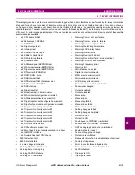
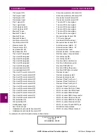
Section 9.2.7: SERVICE SYSTEM STATUS FAILURES on page 9–5 contains the failure and warning codes that appear on
the LCD display. The Information Status command should be used to obtain complete data about the relay status. The
Information Status command can be used at the relay or remotely over a modem link.
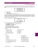
The Information Status command is invoked as follows:
1.
Apply rated DC power to the relay and wait for initialization to complete (if necessary)
2.
Press the INF key, then scroll with the
↑
and
↓
keys until the LCD display indicates: ALPS status
3.
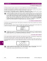
Press the ENT key. The display indicates a failure with the words: STATUS: FAIL
Press the
↑
key to get a detailed report of all the failures. A complete list of the possible errors is found in Section 9.2.7:
SERVICE SYSTEM STATUS FAILURES on page 9–5. The FAIL and WARN messages are also included. Their descrip-
tions may also be displayed LCD display with the Information Status command.
After initial power up or a loss of power exceeding 24 hours, the time and date reset to 00:00:00 01/01/96. All event
and fault data are reset.
LED: Red Status LED
CA: Critical alarm contacts close.
NCA: Non-critical alarm contacts close.
9.2.3 SERVICING A CRITICAL FAILURE
A critical failure indicates total interruption of protection. When a failure occurs on one of the boards (excluding the power
supply), the critical alarm contact opens and the status LED turns red. Remove and reapply DC power to try bring up the
fail message. If the ALPS successfully restarts, the status LED turns green.
If the failure still exists, the status LED remains red and the critical alarm contact open. A FAIL message may also be on the
display. The Fail message indicates the nature of the critical failure. The Fail message remains on the display until a key is
pressed or until the ALPS restarts successfully with no self-test failures. See Section 9.2.7: SERVICE SYSTEM STATUS
FAILURES for the list of mnemonic failure codes and their meanings.
The Information–ALPS Status command can be used to display all the current failures.
Table 9–4: SYSTEM STATUS ERROR MESSAGES
ERROR
INDICATION
DESCRIPTION
WARN
NCA
Warn condition
FAIL
CA/LED
Fail condition
MISC
LED
Miscellaneous condition
NOTE
NOTE
NOTE
Содержание ALPS
Страница 2: ......
Страница 4: ......
Страница 182: ...5 20 ALPS Advanced Line Protection System GE Power Management 5 5 MOB TESTING 5 FUNCTIONAL TESTS FACTORY SETTINGS 5 ...
Страница 200: ...6 18 ALPS Advanced Line Protection System GE Power Management 6 5 ZONE REACH TESTS 6 FUNCTIONAL TESTS USER SETTINGS 6 ...
Страница 346: ...D 4 ALPS Advanced Line Protection System GE Power Management D 1 KEYPAD MENUS APPENDIXD D ...
Страница 352: ...F 2 ALPS Advanced Line Protection System GE Power Management F 1 WARRANTY INFORMATION APPENDIXF F ...
Страница 366: ...xiv ALPS Advanced Line Protection System GE Power Management INDEX INDEX ...

