background image

52

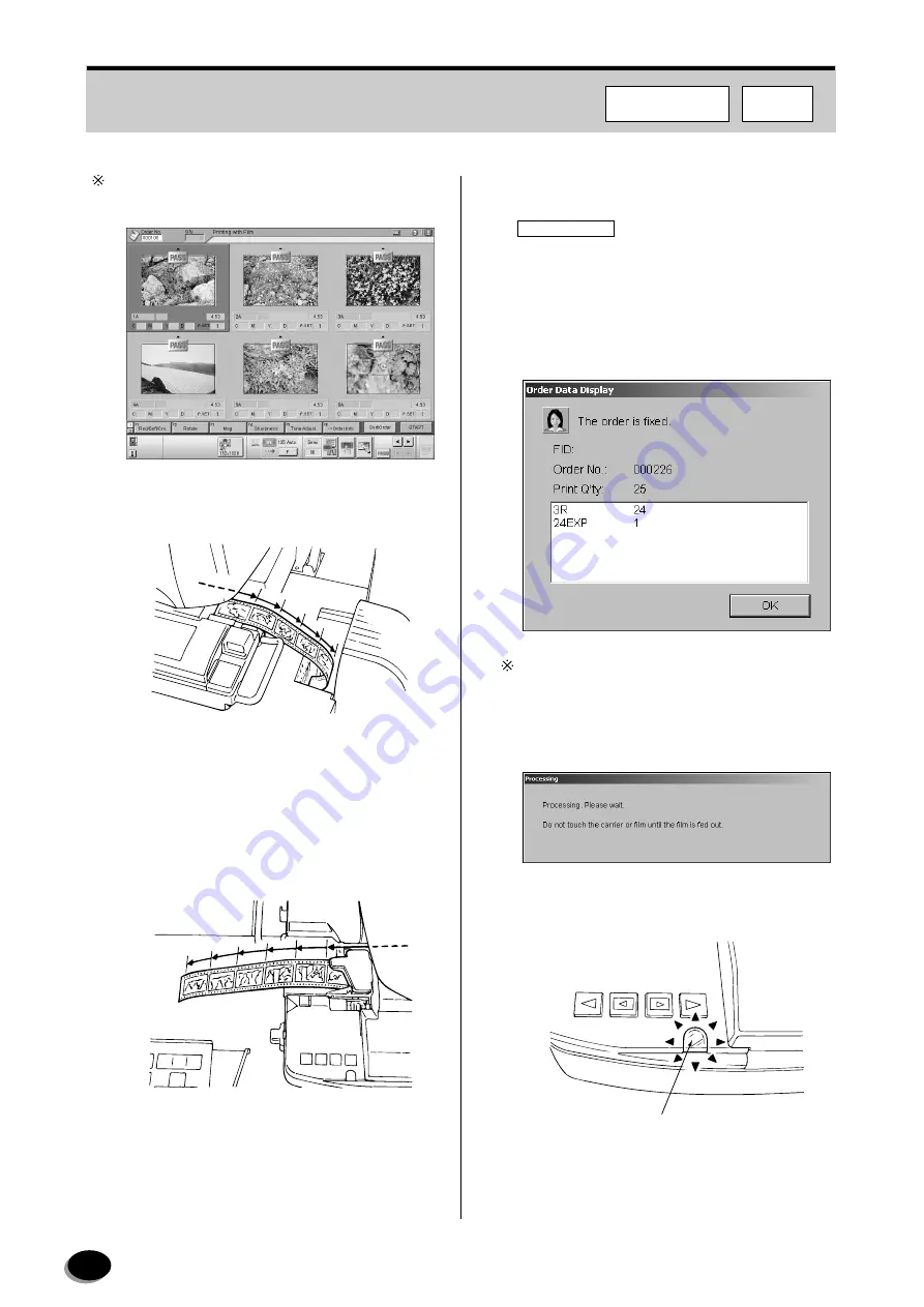
To skip frames not to be printed, select them, then 

press the [PASS] key.

1

Press the [START/ENTER] key if the film feed 
mode is “Semi”.

• One-way scanning mode:

The film is ejected from the right-hand side of the 
film carrier.

• Two-way scanning mode:

The film is ejected from the left-hand side of the 
film carrier.

2

Proceed with scanning of the images.

IMPORTANT

Do not touch the film while it is being fed through 

the carriage.  Pulling out the film at this time will 

cause abnormal printing results.

• When the last frame is scanned, the “Order Data 

Display” dialog box appears automatically.

If the [Scan Cancel] key is pressed during pre-
scanning, the order is not fixed automatically. To fix 
such orders, press the [Sort/Order] button.

• The message shown below appears.

• The green indicator lamp blinks when the fine-

scanning is completed.

Z

2

569

Z

2

065

Indicator Lamp

Z

2

062

FMPC

F355/375/570

distributed by www.minilablaser.com

Содержание Frontier 570

Страница 1: ...ILAB FRONTIER 350 370 355 375 570 Frontier Manager Printer Controller PP3 B1212E FRONTIER 355 375 System DiskVer 1 7 FRONTIER 570 System DiskVer 1 7 FRONTIER 350 370 System DiskVer 7 7 Frontier Manager Printer ControllerVer 2 0 distributed by www minilablaser com ...

Страница 2: ...y result in specification changes without prior notice UNITED STATES OF AMERICA FCC NOTE This equipment has been tested and found to comply with the limits for a Class A digital device pursuant to Part 15 of the FCC Rules These limits are designed to provide reasonable protection against harmful interference when the equipment is operated in a commercial environment This equipment generates uses a...

Страница 3: ...up 21 3 1 1 Starting Up the Imaging Controller 21 3 1 2 Printer LP Start up 22 3 1 3 FMPC Start up 22 3 1 4 Scanner SP Start up 23 3 2 Pre operational Checks in FMPC 24 3 2 1 Processing Solution Temperature Confirmation 25 3 2 2 Control Strip Processing 25 3 2 3 Upkeep Printing 26 3 3 Pre operational Checks in FRONTIER 350 370 29 3 3 1 Mirror Box Cleaning 29 3 3 2 Auto Film Carrier NC240Y Cleaning...

Страница 4: ...ng Down Imaging Controller 67 7 Emergency Stop 69 7 1 Emergency Power OFF in FMPC 69 7 2 Emergency Power OFF in Scanner SP 70 7 3 Manual Shut off of Printer Power 71 7 4 Measures against FMPC Failures 72 7 4 1 To Return to Direct connecting Type in FRONTIER 350 370 72 7 4 2 To Return to Direct connecting Type in FRONTIER 355 375 570 74 8 Setup and Maintenance FRONTIER 350 370 355 375 77 8 1 Operat...

Страница 5: ...2 104 8 2 25 Processing Temperature Setting 463 105 8 2 26 Replenisher Rate Setup 464 105 8 2 27 Evaporation Correction Rate Setting 465 106 8 2 28 Low Volume Setting 466 106 8 2 29 Processor Temperature Calibration 467 107 8 2 30 Processor Input Check 468 108 9 Setup and Maintenance FRONTIER 570 109 9 1 Operator Menu 109 9 1 1 Menu Screen Display 109 9 1 2 Production Information 110 9 1 3 Paper C...

Страница 6: ... 127 9 2 19 Image Position and Tilt Fine Adjustment 458 127 9 2 20 Printer Function Select 459 128 9 2 21 Pump Output Measurement Setting 461 129 9 2 22 Auto Cleaning Output Measurement Setting 462 131 9 2 23 Low Volume Processing Setup 466 132 9 2 24 Processor Temperature Calibration 467 133 9 2 25 Processor Input Check 468 135 9 2 26 Processor Operating Condition Setup 46B 136 10 Error Messages ...

Страница 7: ... result in serious injury or even death CAUTION indicates a potentially hazardous situation which if not avoided may result in minor or moderate injury It may also be used to alert against unsafe practices and property damage only accidents IMPORTANT IMPORTANT describes improper handling procedures that may adversely affect performance or damage the equipment NOTE NOTE designates those items provi...

Страница 8: ...ion from the manufacturer because safety assurance features and other essential functions may be impaired If the machine needs to be modified contact your local dealer x Never remove covers or other parts that are screwed down to avoid the risk of electric shock or injury to personnel If any parts need to be unscrewed contact your local dealer Use only Fujifilm recommended replacement parts If par...

Страница 9: ...0 lux falls on the scanner and printer upper surfaces Should the equipment main body or paper magazine be exposed to direct outside light or strong reflected light use curtains or blinds to shield the equipment from such extraneous light REFERENCE Two 40W fluorescent lamps provide 500 lux of illumination at a distance of 1 meter 3 3 ft NOTE Excessively high indoor illumination levels will adversel...

Страница 10: ...e component names and describes their external and internal structure 2 1 1 System Configuration FMPC FRONTIER 570 2 1 External View FMPC Scanner SP Printer LP Imaging Controller IEEE 1394 Cable IEEE 1394 Cable LAN Cable LAN Cable distributed by www minilablaser com ...

Страница 11: ...11 FMPC FRONTIER 355 375 FMPC Scanner SP IEEE 1394 Cable IEEE 1394 Cable LAN Cable LAN Cable Printer LP Imaging Controller distributed by www minilablaser com ...

Страница 12: ...12 FMPC FRONTIER 350 370 FMPC Scanner SP Printer LP Imaging Controller IEEE 1394 Cable IEEE 1394 Cable LAN Cable LAN Cable distributed by www minilablaser com ...

Страница 13: ... 1GB 400MHz HDD 80GB 7200rpm Partition C Drive 10GB D Drive 70GB Network IntelR Pro 1000MT 10 100 1000 for interface I O Devices 3 5 FDD CD ROM Built in Audio speaker OS Windows XP Professional SP2 English Version Country other than Japan Dimension Width x Height x Depth 181 x 425 x 447 mm Monitor for FMPC and SP3000 FRONTIER Scanner SP Main Control Unit FMPC Switcher Monitor for FMPC and SP 1500 ...

Страница 14: ...st Selects the functions which can be also selected by double clicking the item itself 6 OK button After selecting the function in the Function Selection List then click this button to start the desired function 7 Task Switcher Button Displays the selection windows where you can select the application to be displayed in the foreground 2 2 FMPC Screen 7 5 3 6 4 2 1 distributed by www minilablaser c...

Страница 15: ... restarted while the orders already transferred to the Done list will be deleted after the restart of FMPC 1 Lists up the orders done in the Imaging Controller or FRONTIER When printing is completed they are moved to the Complete List 2 Up to 15 order lines are visible within the list box and up to 999 lines can be accepted 3 To select the order click the line To cancel selecting the line click th...

Страница 16: ...n order to printer is completed Status is not used Other information is the same as that in the Print Waiting List Data is reserved until the system is shut down The width of columns can be changed with the mouse operation 3 Status Displays the current printing status 4 Next Order Stop Resume toggle button Next Order Stop Stops sending images to printer after the current order is transferred to pr...

Страница 17: ...only when Forwarding orders sopped appears in the Status See 3 Status 10 Image Memory Status Displays the current memory consuming status in Printer LP 11 Precedence button Select the order in the upper list and click this button The specified order will be moved to the top of the list and processed preferentially By clicking it again the preferential setting is cancelled 12 Post Check function ke...

Страница 18: ...ssing memory Number of sheets indicated in Waiting status in Sheets being processed IMPORTANT Note that executing of Order Clear deletes all images of the order that is currently being processed 15 Main Menu button Returns to the Main Menu screen distributed by www minilablaser com ...

Страница 19: ...on help Used to forcibly shut down the system in an emergency 4 Status and Setting Check Bar Displays processing conditions Sets printing conditions 5 Sort Order Button Fixes the order and displays the Order Data Display dialog box 6 START Button Fixes the setting number of prints color density corrections etc of the displayed frames and starts printing 7 Remote Error Icon When this icon blincks a...

Страница 20: ...Memory Indicator Emergency Stop Switch Status Display Icon Function Key Display Printing Status Bar Remote Error Icon When this icon blincks an error such as paper width mismatch occurs in the FMPC Take a proper measure to solve problems then start printing again distributed by www minilablaser com ...

Страница 21: ... peripherals are turned on then start up the Imaging Controller 2 The Order Reception screen appears 3 1 System Start up Imaging Controller Start up See 3 1 1 Printer LP Start up See 3 1 2 FMPC Start up See 3 1 3 Scanner SP Start up See 3 1 4 Pre operational Checks in FRONTIER See 3 3 for FRONTIER 350 370 See 3 4 for FRONTIER 355 375 570 Pre operational Checks in FMPC See 3 2 FD019 distributed by ...

Страница 22: ...er switch to STANDBY after the machine starts up FRONTIER 570 1 Check if the built in breaker is turned ON then turn ON the power switch IMPORTANT When starting up the LP5700 set the power switch to STANDBY during the post operational check 3 1 3 FMPC Start up 1 Make sure that the monitor is turned ON and then turn ON the FMPC The FMPC Main Menu screen will appear EZ627 Power Switch EZ626 L2987 NM...

Страница 23: ...the scanner FRONTIER 350 370 FRONTIER 355 375 570 IMPORTANT When starting up the LP5700 set the power switch to STANDBY during the post operational check 2 Main Menu screen appears FRONTIER 350 370 FRONTIER 355 375 570 EZ1192 Z2040 distributed by www minilablaser com ...

Страница 24: ...TIER Perform Pre operational Check in FMPC 1 Press the button of the switcher to display the FMPC main menu screen Also by pressing the Ctrl key twice quickly the display can be switched between FRONTIER and FMPC 2 Select the Pre operational Check on the Main Menu screen and click OK The Pre operational Check screen appears 3 Perform the pre operational checks by following the instructions on the ...

Страница 25: ...sing The processing solution performance is evaluated by processing a control strip measuring the processed strip densities and comparing them with the reference strip densities 1 Process the control strip If not performed click Cancel FRONTIER 350 370 355 375 FRONTIER 570 The Print Calibration screen appears Reference Display Heater OFF OFF ON ON UP Warm up FMPC distributed by www minilablaser co...

Страница 26: ... the base channel paper Each time the paper width and surface are changed print condition setup must be performed 1 Install the master magazine 2 Click Print After about 5 minutes an upkeep print is delivered to the large size tray Densitometer AD100 Densitometer AD200 AD300 3 After the upkeep print has come out click Dens Measurement 4 Adjust the densitometer guide to match the width of the upkee...

Страница 27: ...ge below appears Repeat density measurement from Step 3 If the measurement result is out of the range the message below appears Repeat Steps 2 through 6 until the measurement results fall within the acceptable range The message below appears if the measurement results fall within the range 7 Click OK Indicator Light Ready Measuring Error Power Green On On On Ready Green On Blinks Off Error Red Off...

Страница 28: ...ancel The printing screen appears If the upkeep printing is skipped or after performing the upkeep printing in Setup and Maintenance control returns to the Main Menu screen FMPC distributed by www minilablaser com ...

Страница 29: ...ollowing the instructions on the screen 3 3 1 Mirror Box Cleaning Do not use spray cleaners containing combustible substances as these constitute a fire hazard 1 Pull the lever at the right rear end of the film carrier toward you to release the film carrier 2 Blow off any dirt or dust adhering to the top of the mirror box using the blower brush 3 3 Pre operational Checks in FRONTIER 350 370 Lever ...

Страница 30: ...00 comes in contact with the eyes rinse eyes immediately with large amounts of water and get prompt medical attention 1 Pull the release lever as shown in the figure to release the pressure cover 2 Blow off any dirt or dust adhering to the sensors glass surfaces and film guide sections using the blower brush IMPORTANT Take care not to scratch or mark the sensors Dirt or dust on the sensor or guide...

Страница 31: ...lens cleaning cloth 7 Remove any dirt or dust adhering to the groove in the mask using a cotton swab and blower brush 8 Reinstall the mask 9 Blow off any dirt or dust adhering to the opening in the pressure cover using the blower brush 10 Close the pressure cover Roller Cleaning Knob Roller Swab EZ1158 Mask EZ1301 Lens Cleaning Cloth Diffusion Plate EZ1302 Mask Swab EZ1835 Mask EZ1321 Pressure Cov...

Страница 32: ...tton swab Store magnet cleaner MC 100 in a safe place under low temperature Take care not to inhale its vapor If you have inhaled the vapor excessively immediately move to a place having fresh air If magnet cleaner MC 100 comes in contact with the eyes eyes rinse immediately with large amounts of water and get prompt medical attention 1 Pull the release lever as shown in the figure to release the ...

Страница 33: ...w off any dirt or dust adhering to the inside 6 Remove any dirt or dust adhering to the guide rollers using a cotton swab 7 While rotating the roller cleaning knob use a cotton swab moistened with magnet cleaner MC 100 to remove any dirt or dust adhering to the rollers 8 Remove the mask Sensors Sensors Blower Brush EZ632 Winding Section EZ1013 Blower Brush EZ1014 Swab EZ1324 Swab Roller Cleaning K...

Страница 34: ... off any dirt or dust adhering to the opening in the pressure cover using the blower brush 13 Close the pressure cover 14 Align the mark on the film carrier with the rail and push the carrier all the way in 15 Click OK The Scanner Correction screen appears Lens Cleaning Cloth Diffusion Plate EZ1298 Mask Swab EZ1833 Mask EZ1299 Pressure Cover Blower Brush EZ1832 Rail Auto Film Carrier NC135Y Mark E...

Страница 35: ...appears wait until it disappears A message appears and the correction is automatically started After the completion of the correction the Skip button changes to the End button 2 Click END The printing screen appears Control returns to the Main Menu screen when skipping the scanner correction or when performing the scanner correction in the Setup and Maintenance F350 370 distributed by www minilabl...

Страница 36: ... operational checks by following the instructions on the screen Basic operation of the pre operational checks Perform Items 1 to 3 in order To proceed to the next item click the Next Page button When the Next Page button is no longer displayed click the OK button Be sure to complete all items before printing To display the No 1 to No 3 screens after completing the pre operational checks The 1 Diff...

Страница 37: ...ng the carrier hold the handles with both hands in a balanced manner 3 Blow off any dirt or dust adhering to the top and bottom of the diffusion box using the blower brush IMPORTANT If the diffusion box is not cleaned dust or dirt on it may appear on the prints Take care not to damage the top and bottom of the diffusion box 4 Click the Next Page button The second screen of Diffusion Box Check appe...

Страница 38: ... the holes 7 Click the OK button The first screen of 2 Film Carrier Cleaning appears 3 4 2 Auto Film Carrier NC100AY Cleaning Clean the auto film carrier NC100AY IMPORTANT If the auto film carrier NC100AC is not cleaned any dirt adhering to the film feed section may cause film feed errors scratches or damage to film 1 Open the Carrier cover LED Board Cover Blower Brush EZ2010 Diffusion Box Hole Ho...

Страница 39: ...rwise the glass surfaces may be damaged 4 Click the Next Page button The second screen of 2 Film Carrier Cleaning appears 5 Remove the 135 insertion section upper guide 6 Blow off any dirt or dust adhering to the film guide sections using the blower brush IMPORTANT Dust or dirt on a film guide section may scratch or mark the films 7 Click the Next Page button Pressure Cover Pressure Cover Release ...

Страница 40: ...urfaces of the feed lanes Otherwise the glass surfaces may be damaged 9 Click the Next Page button The fourth screen of 2 Film Carrier Cleaning appears 10 Remove any dirt or dust adhering to the dust removal brushes and rollers Do not drop the 135 insertion section upper guide on the glass surfaces of the feed lanes Otherwise the glass surfaces may be damaged Blower Blush 135 Full Lower Mask Diffu...

Страница 41: ...ction Perform scanner correction to carry out the automatic correction of the scanner conditions in order to obtain consistent print quality 1 Hold the film carrier as shown align the mark on the film carrier with the mark on the scanner section and then push the carrier in until it stops When installing the carrier keep the carrier horizontal If the carrier is installed with the rear side raised ...

Страница 42: ...size is used perform scanner correction by following the procedure below 1 Pull the film carrier lock release lever to release the film carrier 2 While holding the handles pull the film carrier forward to remove it When moving the carrier hold the handles with both hands in a balanced manner 3 Open the upper cover of the multi film carrier 4 Mount the calibration mask on the multi film carrier 5 C...

Страница 43: ...l multi film carrier 120 220 size is used perform scanner correction by following the procedure below 1 Pull the film carrier lock release lever to release the film carrier 2 While holding the handles pull the film carrier forward to remove it 3 Remove the 135 diffusion box 4 Install the 120 diffusion box Marks Multi film Carrier MFC10AY Z2510 Handles Multi film Carrier MFC10AY Film Carrier Lock R...

Страница 44: ...canner section and then push the carrier in until it stops 9 Click the Start button Scanner correction is started After the completion of the correction the message The scanner correction is completed appears 5 Click the OK button Control returns to the Order Information screen Multi film Carrier MFC10AY Upper Cover Calibration Mask Z2074 Marks Multi film Carrier MFC10AY Z2510 F355 375 570 distrib...

Страница 45: ... print size selected Upper The upper paper magazine is selected Lower The lower paper magazine is selected When the paper types of two magazines are differrent make sure to select Upper or Lower If paper has come to an end in the paper magazine selected when the upper and lower magazines are the same paper size in the Auto mode the message Paper end process completed in upper lower magazine Paper ...

Страница 46: ...process the any of the orders that are not printed yet in the Done list may not be printed Please perform printing process for these orders again 5 1 1 DSC Printing from Imaging Controller Example Imaging Controller Operation 1 Set the media in the drive 2 In the OUTPUT field select the FMPC device ex FMPCsRGB FMPC 3 In the INPUT field click the icon of the media you inserted 4 On the DSC Print Se...

Страница 47: ...e DSC date is to be printed on the print or not If you want to create an index print only specify number of index or large index prints while entering 0 in Print Q ty box 8 Select the resizing specification See 2 2 2 Resize in Instruction Manual Service Specification Select the images Select the print size Specify if or not the index large index is to be outputted size and if DSC date is to be pri...

Страница 48: ...rinting is automatically started on the FMPC If the Resume button appears at the bottom of the screen click it to switch to the Resume button So printing is started To stop printing from the Imaging Controller click the Next Order Stop button then delete the order in the Imaging Controller The orders may not be deleted correctly in FMPC when the status is displayed or when trying to delete the ord...

Страница 49: ... operation may be stopped If this occurs open the Printing Status screen and then resume printing IMPORTANT If a jamming occurs in the printer LP during the printing process the any of the orders that are not printed yet in the Done list may not be printed Please perform printing process for these orders again 1 The scanner pre scans film images when the film is loaded The images of the first 6 fr...

Страница 50: ...t this time will cause abnormal printing results 4 When the last frame is completed the sort dialog box appears automatically 5 The message shown below appears 6 The green indicator blinks when the fine scanning is completed The order is registered in the FMPC IMPORTANT The orders that are registered in the FMPC cannot be deleted with the Print Stop key To delete them select orders one by one then...

Страница 51: ...When performing the film printing from the scanner SP make sure that the Printing Status screen is opened after the pre operational check is completed If the printing is started before the Printing Status screen does not appear the operation may be stopped If this occurs open the Printing Status screen and then resume printing IMPORTANT If a jamming occurs in the printer LP during the printing pro...

Страница 52: ...NT Do not touch the film while it is being fed through the carriage Pulling out the film at this time will cause abnormal printing results When the last frame is scanned the Order Data Display dialog box appears automatically If the Scan Cancel key is pressed during pre scanning the order is not fixed automatically To fix such orders press the Sort Order button The message shown below appears The ...

Страница 53: ... screen is opened after the pre operational check is completed If the printing is started before the Printing Status screen does not appear the operation may be stopped If this occurs open the Printing Status screen and then resume printing 4 Printing is automatically started on the FMPC If the Resume button appears at the bottom of the screen click it to switch to the Next Order Stop button So pr...

Страница 54: ...e mismatched paper setting To replace the magazine with the correct one click the OK button Unless the orders with mismatched paper are urgent ones it is recommended to print the possible orders first then the remaining orders after replacing the magazine 5 2 2 When W 1627 Message Dialog Appears This message appears when mismatching of surface or emulsion type occurred between the upper and lower ...

Страница 55: ...m the first frame again Click the OK button then to replace the magazine with correct one and then to start printing again Order Outputs forcibly the current order Image Outputs forcibly the current image OK Replace the magazine with the correct one then click this button to start printing Before clicking the OK button make sure that the printer LP is initialized Abort Returns to the printing scre...

Страница 56: ...s performed with the print size from entry No 51 to the last on the 424 Print Size Setup screen When the above is done together with the index print only the billing for latter is outputted from the PU800B When the DSC printing is performed in the Imaging Controller by using the print size of entry No 50 the total of DSC print basic price and printing price is printed on the same column of the rec...

Страница 57: ...n the printing screen select the Quit 1 in the pull down menu Control returns to the Main Menu screen 2 Select the Post operational Checks and click OK 6 1 Post operational Checks and Shut down in FRONTIER 350 370 Post operational Checks and Shut down in FRONTIER See 6 1 for FRONTIER 350 370 See 6 2 for FRONTIER 355 375 570 Post operational Check and Shut down in FMPC See 6 3 Shutting Down Imaging...

Страница 58: ... 6 Clean around the machine and then click OK The Production Information screen appears Select the Negative Reversal Digital Image or All from the Input Type box to display production information respectively IMPORTANT The printing information from the DSC import is not counted in this screen Check and save this information in the Production Information in the FMPC Release Lever Pressure Cover EZ1...

Страница 59: ...on window appears 2 Click OK Data is cleared and the clearing date appears in the From box 8 Click OK The data is cleared and cleared date is displayed If the post operational check is done after zero hour on the day the Timer ON time is set to the next day In this case set it to this day IMPORTANT The next timer ON date cannot be changed on this screen To change it open 4 Setup and Maintenance 1 ...

Страница 60: ...Order Information screen click the MAIN MENU button The main menu screen appears 2 Click the Post operational Check button The 1 Film Carrier Cleaning screen appears 6 2 1 Cleaning the Auto Film Carrier NC100AY Clean the auto film carrier NC100AY IMPORTANT If the auto film carrier NC100AY is not cleaned any dirt adhering to the film feed section may cause film feed errors scratches or damage to fi...

Страница 61: ...e pressure cover 5 Use a cotton swab moistened with alcohol solution 50 ethanol to remove any dirt or dust adhering to the rollers Hold the foot of the cotton swab and rub it against the magnetic head firmly 6 Click the Next Page button The second screen 1 Film Carrier Cleaning appears Handles Auto Film Carrier NC100AY Film Carrier Lock Release Lever Z2051 Carrier Cover EZ053 EZ054 Pressure Cover ...

Страница 62: ... dust adhering to the winding section roller using a lens cleaning cloth while rotating the roller cleaning knob 11 Close the winding section cover 12 Close the pressure cover and press it down until it clicks 13 Close the carrier cover 14 Click the OK button The Clearing Around the Machine screen appears Roller Cleaning Knob Rollers 15 Cotton Swab EZ2003 Lens Cleaning Cloth Winding Section Cover ...

Страница 63: ...Film type box to display production information respectively IMPORTANT The printing information from the DSC import is not counted in this screen Check and save this information in the Production Information in the FMPC 1 Record the daily processing volume data To clear the data follow the steps below 1 Click the Clear button The Clear production information dialog box appears 2 Click the OK butto...

Страница 64: ...e 6 Shut Down screen if Cancel is clicked When restarting the system immediately after the scanner is turned OFF be sure to wait for more than 12 seconds before pressing the START switch Note that the system cannot be started unless more than 12 seconds have elapsed because of the function of the protection circuit F355 375 570 distributed by www minilablaser com ...

Страница 65: ...w the steps blew 1 Click the FD Save button 2 Insert the FD into the FD drive then click the OK button The data is saved in the FD 3 Remove the FD from the drive then click the OK button IMPORTANT Make sure that the FD is removed from the FD drive If remains in the drive the FMPC is not started up during the next restart 1 Click Clear The Clear production information window appears 2 Click OK Data...

Страница 66: ...be changed change them according to the instructions as shown below 1 Click Modify The Next Timer ON Date Time Change window appears 2 Select the box to be changed and change date and time 3 Click OK The dialog box disappears 6 Click Shut Down The data is stored onto the hard disk The processor auto cleaning is performed and the processor automatically changes to STANDBY Control returns to the Mai...

Страница 67: ...ed 3 Operation returns to the Desktop of Windows NT Windows 2000 To shut down the computer click the Exit button while pressing the Shift button 4 Select Shut Down from the Start menu at the bottom of the desktop Windows NT Windows 2000 5 In case of Windows NT Select the Shut down the computer and click the Yes button Windows NT 6 4 Shutting Down Imaging Controller Click IC distributed by www mini...

Страница 68: ... click the OK button Windows 2000 7 Turn OFF the media units PC card reader CD R Zip MO drives etc 8 Turn OFF the flatbed scanner 9 Turn OFF the monitor 10 Turn OFF the Imaging Controller FD034 FD257 FD036 FD032 IC distributed by www minilablaser com ...

Страница 69: ... The Emergency Stop dialog box appears 2 Click OK The emergency stop process starts and then the FMPC is turned OFF 3 Press the system start switch to start the system again 4 Restart the FRONTIER scanner SP IMPORTANT When restarting the FMPC the SP scanner must be also restarted If problems persist or if an abnormality still exists consult your technical representative 7 1 Emergency Power OFF in ...

Страница 70: ...he Start button If an error occurs after the restart consult your technical representative FRONTIER 350 370 1 Click the emergency stop switch in the upper right hand corner of the screen The Emergency Stop dialog box appears 2 Click OK The emergency stop process starts and then the scanner SP is turned OFF 3 Press the Start button to start up the FRONTIER again If an error occurs after the restart...

Страница 71: ... the built in circuit breaker 3 Turn OFF the main power circuit breaker 4 Consult your technical representative FRONTIER 570 1 Immediately turn the power switch to STANDBY 2 Turn OFF the built in circuit breaker 3 Turn OFF the main power circuit breaker 4 Consult your technical representative 7 3 Manual Shut off of Printer Power Power Switch EZ626 Built in Circuit Breaker EZ674 Power Switch L2988 ...

Страница 72: ...4 Setup and Maintenance then click the OK button If the initializing of printer failed message appears click the Retry button to clear it and then perform the procedures 2 In the Login dialog select SE2 as user name and enter the password 7777 and then click the OK button 3 Select 41 System Operation Setup and Check 41F Installation Information Setup then click the Start button 4 The 41F Installat...

Страница 73: ...om the printer and the one from the scanner to the connectors on the same board in the FMPC 10 Insert the FD containing no system program into the FD drive of the FMPC and then turn it ON Make sure that the FD does not contain the executable file After start up the error message Non System disk or disk error appears and the Windows is not started up 11 Turn on the printer then set the switch to ST...

Страница 74: ...ONTIER 355 375 570 To return to the direct connecting type in FRONTIER 355 375 use the following procedures 1 On the Main Menu screen in the scanner SP click the Setup and Maintenance button If the Setup and Maintenance screen does not appear start up the FRONTIER in the stand alone mode 2 Enter the password 7777 and then click the OK button 3 Select 01 System Operation Setup and Check 0140 Instal...

Страница 75: ...the scanner 7 Switch the display to FMPC by pressing the button on the switcher The display can be switched also by pressing the Ctrl key twice swiftly 8 On the Main Menu screen in the FMPC select 3 Post operational Check then click the OK button then shut down the FMPC and printer LP 9 Disconnect the IEEE1394 cable from the scanner SP MP019 MP047 FMPC F355 375 570 distributed by www minilablaser ...

Страница 76: ...emotely by turning on the scanner SP 12 Turn on the scanner SP 13 After the restart the Main Menu screen appears IMPORTANT To perform printing from the Imaging Controller the FMPC logical device name on the administration screen in each DI application on the Imaging Controller must be set up MP048 Z2040 FMPC distributed by www minilablaser com ...

Страница 77: ...lect the 4 Setup and Maintenance and click the OK button The Login dialog box appears Leave blank in the Password box when accessing to the Operator in the User Name box 2 Click OK The menu screen of the 4 Setup and Maintenance appears The sub menu disappears by clicking the button at the left of each item and reappears by clicking the button 8 1 Operator Menu distributed by www minilablaser com ...

Страница 78: ...an be changed by selecting Negative Reversal Digital Image or All from the Input Type box 4 To clear the data follow the steps below 1 Click Clear The Clear production information dialog box appears 2 Click OK The production data is erased 5 Click OK Operation returns to the 4 Setup and Maintenance screen 6 Select the END 1 on the menu bar Operation returns to the Main Menu screen distributed by w...

Страница 79: ...1 2 Select the 1 Paper Condition Setup 3 Click START The 421 Paper Condition Setup screen appears 4 Select the Magazine Upper or Magazine Lower to be set up 5 Click Print After about 5 minutes an upkeep print is delivered to the large size tray Densitometer AD100 Densitometer AD200 6 After the condition setup print has come out press the Dens Measure button distributed by www minilablaser com ...

Страница 80: ... densitometer If the message below appears click OK and repeat the density measurement from Step 6 The measurement is automatically started and the density measurement result is displayed 10 Click OK The density measurement result disappears Indicator Light Ready Measuring Error Power Green On On On Ready Green On Blinks Off Error Red Off Off On Guides Densitometer EZ634 Densitometer Condition Set...

Страница 81: ...ce screen appears 13 Select the END 1 on the menu bar Control returns to the Main Menu 8 1 4 Processing Solution Temperature Check 1 Open the 4 Setup and Maintenance menu screen see Section 8 1 2 Select the 2 Processor Temperature Check 3 Click START The 422 Processor Temperature Check screen appears 4 Click OK Operation returns to the 4 Setup and Maintenance screen distributed by www minilablaser...

Страница 82: ...g them with the reference strip densities 1 Take the control strip package out of the freezer and leave it for about one hour to bring it to room temperature 2 Take the inner bag out of the control strip package and place it on the control strip holder with its seamed surface up and put them both in the dark box Close the dark box cover EZ1841 Seamed Surface Control Strip Holder Control Strip Inne...

Страница 83: ...ake the control strip holder out of the dark box 6 Return the control strip package to the freezer 7 Open the 4 Setup and Maintenance menu screen see Section 8 1 8 Select 3 Control Strip Processing and click START The 423 Control Strip Processing screen appears 9 Click OK to start the control strip processing The message Processing the control strip appears The message Set Holder appears on the op...

Страница 84: ...ars on the screen 12 Remove the control strip holder from the port in the processor cover 13 Click OK The message is cleared 14 Click Cancel Control returns to the 4 Setup and Maintenance screen For the daily morning pre operational checks operation returns to the Printing Condition Upkeep 15 Select the END 1 on the menu bar Control returns to the Main Menu screen Control Strip Holder Port Cover C...

Страница 85: ...zer 10 C 14 F or below Storage at room temperatures leads to deterioration in performance Moisture condensation occurs if the control strips are processed immediately after they have been taken out of freezer This may give rise to processing unevenness Do not open the folded end of the inner bag under any light or the control strips may become fogged and rendered useless 8 1 6 DIC Order Back Print...

Страница 86: ...vent any solution from coming in contact with the body Always wash hands well after handling processing solutions 1 Prepare a measuring cylinder 2 Remove the sub tank cover 3 Open the 4 Setup and Maintenance menu screen see Section 8 1 4 Select 1 Pump Output Measurement Setting and press the START key The 461 Pump Output Measurement Setting screen appears The cursor is located on the Measured valu...

Страница 87: ... the output 9 Pour the replenisher solution from the measuring cylinder into the waste recovery tank 10 Select the Measured value box for PS R and enter the recorded output value using numeric keys The machine automatically measures and adjusts the pump outputs for P1 R P2 RA and P2 RB 11 Click OK Operation returns to the 4 Setup and Maintenance screen 12 Select the END 1 on the menu bar Control r...

Страница 88: ...ys wash hands well after handling the processing solutions 1 Prepare two measuring vessels to measure the auto cleaning pump output 2 Remove the processor cover 3 Remove the dryer entrance rack cover 4 Release the lock release lever and remove the No 1 crossover rack 5 Release the locking hook and remove the two auto cleaning nozzles from the No 1 crossover rack 6 Drain the auto cleaning nozzles P...

Страница 89: ...improperly the washing solution will splash 9 Open the 4 Setup and Maintenance menu screen see Section 8 1 10 Select 2 Auto cleaning Output Measurement Setting and click START The 462 Auto cleaning Output Measurement Setting screen appears The cursor is located on the Measured value for P1 11 Click Start for P1 The alarm beeps intermittently for 10 seconds Click Cancel to stop the operation The al...

Страница 90: ...ing rack 16 Select Measured value for P1 and enter the recorded output value using numeric keys or the and keys 17 Select P2 PS1 and PS3 and perform Steps 11 through 16 successively 18 Click OK Control returns to the 4 Setup and Maintenance screen 19 Select the END 1 on the menu bar Control returns to the Main Menu screen 20 Reinstall the dryer entrance rack cover and the processor cover Lock Rele...

Страница 91: ...ox The Sub item List box of the selected item appears 4 To perform the desired operation double click on the operation or select the operation and click START The operation screen appears 5 Perform the operation by following the instructions that appear 6 Upon completion of the operation click End OK or Cancel 4 Setup and Maintenance screen appears 7 Click END on the menu bar Operation returns to ...

Страница 92: ...he data can be cleared in this menu Input Type Negative Reversal Digital Image All 1 Record the production information 2 To clear the data follow the steps below 1 Use Input Type to choose which data you wish to clear 2 Then press click Clear The Clear production information dialog box appears 3 Click OK The data is cleared and date of clearance appears 3 Click OK Operation returns to the 4 Setup ...

Страница 93: ...calendar timer is set to 5 00 AM and night time preheating is turned ON at 3 30 AM all the power will be shut down two hours later at 5 30 AM NOTE Night time preheating is usually conducted when the room temperature drops below 10 C 50 F at night and the temperature is not controlled for 8 or more hours 1 Select YES for Preheat Setting The 1st and 2nd preheat setting boxes appear 2 Move the cursor...

Страница 94: ...of date and time 1 Click Log Info The Log File Re reading Check dialog box appears 2 Click OK The log file is reloaded 3 Click Accum Info Accumulated error information is displayed in order of code and frequency 4 Click Log Information Operation returns to the Error log information screen 5 Click OK Operation returns to the 4 Setup and Maintenance screen distributed by www minilablaser com ...

Страница 95: ...urns to the 4 Setup and Maintenance screen 8 2 7 Data Backup 417 Selection 4 Setup and Maintenance 1 System Operation Setup and Check 7 Data Backup Procedure Make a backup of unit data stored in the hard disk of the main control unit after changing data of the Setup and Maintenance mode in case unit data is damaged 1 Prepare the data backup floppy disk FMPC or LP1500 LP2000 2 Insert the disk into ...

Страница 96: ...ins in the drive the FMPC is not started up during the next restart 8 2 8 DI Manager Administrative Setting 41l Set the time to delete the order that is completed on the DI Controller Selection 4 Setup and Maintenance 1 System Operation Setup and Check I DI Manager Administrative Setting Procedure 1 Select the time to be deleted the completed order on the DI controller 2 Click OK Operation returns...

Страница 97: ... 1580 ON BL 4 102C 1020 1520 ON BL 5 102P 1020 2540 ON BL 6 102H 1020 1780 ON BL 7 3R 1270 890 ON BL 8 3RBD 1270 890 OFF BD 9 5R 1270 1780 OFF BL 10 5RBD 1270 1780 OFF BD 11 4R 1520 1020 ON BL 12 4RBD 1520 1020 OFF BD 13 6R 1520 2030 OFF BL 14 6RW 1520 2160 OFF BL 15 8R 2030 2540 ON BL 16 8RW 2030 3050 OFF BL 17 A5 2100 1480 OFF BL 18 A4 2100 2970 OFF BL 19 8R1 2540 2030 OFF BL 20 10R 2540 3050 OF...

Страница 98: ...o restart the FMPC and to check if the printing status screen is opened IMPORTANT When using the PU800B the billing information is not outputted when printing is performed with the print size from entry No 51 to No 100 3 Click OK Operation returns to the 4 Setup and Maintenance screen 8 2 13 DIC Order Back Printing Setup See 8 1 6 DIC Order Back Printing Setup 8 2 14 Paper Magazine Registration 45...

Страница 99: ...Z854 Paper Shaft Screws 2 Flange EZ855 1 89 Glossy A 180 180 55 0 62 0 2 102 Glossy A 180 180 55 0 62 0 3 117 Glossy A 180 180 55 0 62 0 4 127 Glossy A 180 180 55 0 62 0 5 152 Glossy A 180 180 55 0 62 0 6 89 Glossy A 180 180 55 0 62 0 7 102 Glossy A 180 180 55 0 62 0 8 117 Glossy A 180 180 55 0 62 0 9 127 Glossy A 180 180 55 0 62 0 10 152 Glossy A 180 180 55 0 62 0 11 203 Glossy A 90 90 55 0 67 0 ...

Страница 100: ...e of 381mm Measured Value of 127mm Example Measured Value of 381mm 380 0mm Measured Value of 127mm 126 4mm Adding Value 254 380 126 4 0 4 6 Add the Adding Value to the value in the Fine adjust value and enter it in the Fine adjust value box Example Fine adjust value 1 0mm Adding Value 0 4mm New Fine Adjust Value 1 0 0 4 1 4 7 In Menu 455 Paper Feed feed paper with 127 0mm feed length 8 Measure the...

Страница 101: ...er The optimal temperature setup is started and the result is displayed after 5 minutes 2 Click End Operation returns to the 4 Setup and Maintenance screen 8 2 17 Paper Feed 455 Selection 4 Setup and Maintenance 5 Printer Adjustment Maintenance 5 Paper Feed Procedure Paper is fed without printing 1 Set the number of prints feed length and select magazine Quantity 1 to 999 Feed Length 82 5 to 381 0...

Страница 102: ... temperatures are updated every 5 seconds Keep the Abnormal temp detection to ON 1 Click OK Operation returns to the 4 Setup and Maintenance screen 8 2 19 Printer Input Check 457 Selection 4 Setup and Maintenance 5 Printer Adjustment Maintenance 7 Printer Input Check Procedure Check the status of the sensors 1 Click End Operation returns to the 4 Setup and Maintenance screen distributed by www min...

Страница 103: ...t BD and Right BD columns 2 To move the image in the feed direction decrease the value in the Sub scanning Y 3 To move the image in the reverse direction increase the value in the Sub scanning Y 4 To move the image in the rear direction decrease the value in the Main scanning X 5 To move the image in the front direction increase the value in the Main scanning X NOTE Adjusting Range 30mm to 30mm 5 ...

Страница 104: ... to be changed 2 Enter the precut length in the Precut length box 3 Click Set The precut length in the table is changed to the length entered 4 Click End Operation returns to the 4 Setup and Maintenance screen NOTE A pre cut length less than 152mm may cause paper jam etc 8 2 23 Pump Output Measurement Setting 461 See 8 1 7 Replenisher Pump Output Measurement 8 2 24 Auto cleaning Output Measurement...

Страница 105: ...creen 8 2 26 Replenisher Rate Setup 464 Selection 4 Setup and Maintenance 6 Processor Adjustment Maintenance 4 Replenisher Rate Setting Procedure Set the replenishment amount 1 Enter the numerical values of the P1 R P2 R and PS R replenishment amount 2 Click OK Operation returns to the 4 Setup and Maintenance screen Range Default Value P1 30 0 to 40 0 38 5 P2 30 0 to 40 0 38 0 PS 30 0 to 40 0 38 0...

Страница 106: ...4 Setup and Maintenance screen 8 2 28 Low Volume Setting 466 Selection 4 Setup and Maintenance 6 Processor Adjustment Maintenance 6 Low volume Setting Procedure Set the low volume processing data 1 Select YES to Low volume 2 Enter value in the Min processing amount box Range 0 0 to 15 0 3 Enter value in the Min processing amount last 8 days box Range 0 0 to 99 9 4 To clear the data press the Clear...

Страница 107: ...rculation filter and place it on the tray NOTE Do not let the solution drip or run 3 Measure the temperature of the processing solution and record it 4 Reinstall the filter by aligning the fastening tab with the notch and turn it 90 clockwise 5 If the Setting temperatures differ from the values displayed move the cursor to the Measured value and enter the values recorded in Step 3 Range 0 0 to 99 ...

Страница 108: ...en 8 2 30 Processor Input Check 468 Selection 4 Setup and Maintenance 6 Processor Adjustment Maintenance 8 Processor Input Check Procedure Check the status of the sensors 1 Click End Operation returns to the 4 Setup and Maintenance screen distributed by www minilablaser com ...

Страница 109: ...ct the 4 Setup and Maintenance and click the OK button The Login dialog box appears Leave blank in the Password box when accessing to the Operator in the User Name box 2 Click OK The menu screen of the 4 Setup and Maintenance appears The sub menu disappears by clicking the button at the left of each item and reappears by clicking the button 9 1 Operator Menu distributed by www minilablaser com ...

Страница 110: ... the FD follow the steps below 1 Click the FD Save button 2 Insert the FD into the FD drive then click the OK button The data is saved in the FD 3 Remove the FD from the drive then click the OK button 5 To clear the data follow the steps below 1 Click Clear The Clear production information dialog box appears 2 Click OK The production data is erased 6 Click OK Operation returns to the 4 Setup and M...

Страница 111: ...pears 4 Select the upper or lower magazine and then click the Print button After about 5 minutes a condition setup print is delivered to the large size tray 5 Adjust the densitometer guide to match the width of the condition setup print 6 Insert the condition setup print into the densitometer until it stops 7 Click the Dens Measure button Density measurement is automatically started Guides Densito...

Страница 112: ...dition setup result dialog box disappears 9 Click the Close button Control returns to the Setup and Maintenance menu 9 1 4 DIC Order Back Printing Setup 1 Open the 4 Setup and Maintenance menu screen see Section 8 1 2 Select O DIC Order Back Print Setup and then click START 3 Select Yes for Back Print and then click OK 4 Select the END 1 on the menu bar If No is selected the back printing is not p...

Страница 113: ...ations select the button of the desired item from the Item List box The Sub item List box of the selected item appears 4 To perform the desired operation double click on the operation or select the operation and click START The operation screen appears 5 Perform the operation by following the displayed instructions that appear 6 Upon completion of the operation click End OK or Cancel 4 Setup and M...

Страница 114: ...can be cleared on this menu Input Type Negative Reversal Digital Image All 1 Record the production information 2 To clear the data follow the steps below 1 Use Input Type to choose which data you wish to clear 2 Then press click Clear The Clear production information dialog box appears 3 Click OK The data is cleared and date of clearance appears 3 To save the data in the FD follow the steps below ...

Страница 115: ...on Information Procedure This menu is to view accumulated amount of production not to be cleared The whole production information can be confirmed by selecting All in Input Type 1 Record the production information 2 To save the data in the FD follow the steps blew 1 Click the FD Save button 2 Insert the FD into the FD drive then click the OK button The data is saved in the FD distributed by www mi...

Страница 116: ...mes of the printer processor are set NOTE The timer ON date time of the scanner cannot be set 1 To update Present time setup change the date and time and click the OK button NOTE To cancel the update press the Cancel button 2 To change the timer ON date and time check the day of the week and enter the time in the Timer ON Date Time Setting box 3 Set the preheat timer by following the steps below i...

Страница 117: ... only once set the same time for both the first and second times Select NO when no preheat timer is used The second preheating timer is ignored if the first and second times overlap Example 1st preheat time 2 00 AM 2nd preheat time 3 00 AM With the above settings night time preheating will occur from 2 00 AM to 4 00 AM 2 hours 4 Click the OK button Operation returns to the menu screen 9 2 6 Error ...

Страница 118: ...tion Confirmation 416 Selection 4 Setup and Maintenance 1 System Operation Setup and Check 6 Installation Information Reference Procedure Check the installation information 1 Confirm the installation information 2 Click the Option button Optional Device Reference dialog box appears 3 Check if External File I O Variety Print etc are used 4 Click the OK button The dialog box disappears 5 Click the O...

Страница 119: ... 1 Prepare a floppy disk for data backup when backing up film scanner or printer processor data 2 Move the cursor to the Destination box and select FMP Controller or Printer 3 Click the OK button Making the backup of the data message appears 4 Insert the floppy disk into the floppy drive of the main control unit 5 Click the OK button 6 Upon completion of the backup click the Cancel button Operatio...

Страница 120: ... Print Size Width 0 1mm Length 0 1mm Display Border 1 89C 89 0 127 0 ON BL 2 89P 89 0 254 0 ON BL 3 89H 89 0 158 0 ON BL 4 102C 102 0 152 0 ON BL 5 102P 102 0 254 0 ON BL 6 102H 102 0 178 0 ON BL 7 3R 127 0 89 0 ON BL 8 3RBD 127 0 89 0 OFF BD 9 5R 127 0 178 0 OFF BL 10 5RBD 127 0 178 0 OFF BD 11 4R 152 0 102 0 ON BL 12 4RBD 152 0 102 0 OFF BD 13 6R 152 0 203 0 OFF BL 14 6RW 152 0 216 0 OFF BL 15 8...

Страница 121: ...screen 9 2 12 DIC Order Back Printing Setup See 9 1 4 DIC Order Back Printing Setup 9 2 13 Paper Magazine Registration 451 Selection 4 Setup and Maintenance 5 Printer Adjustment Maintenance 1 Paper Magazine Registration NOTE This menu cannot be used while the processor is operating Procedure Register the paper magazine to be used ID Enter the magazine ID Width Enter the paper width mm Paper Select...

Страница 122: ...leasing the latches 2 Remove the two screws and adjust the width of the paper guides Then tighten the two screws Do not try to remove the other parts and covers secured by the screws NOTE Use the appropriate guides according to paper width Guide C is available as an optional accessory 3 Loosen the four screws securing the paper flanges 4 Align the holes in the paper flanges with the paper width ma...

Страница 123: ...ns to the menu screen Magazine ID Paper Width mm Paper Type Paper Length m Remaining Length m Line Speed 1 89 0 Glossy F 186 186 High 2 102 0 Glossy A 186 186 Low 3 117 0 Glossy A 186 186 Low 4 127 0 Glossy F 186 186 High 5 152 0 Glossy F 186 186 High 6 203 0 Glossy A 90 90 Low 7 210 0 Glossy A 90 90 Low 8 254 0 Glossy A 90 90 Low 9 279 0 Glossy A 90 90 Low 10 305 0 Glossy A 90 90 Low 11 89 0 Glos...

Страница 124: ... Enter new magazine ID in the Magazine ID box 3 Select Upper for Magazine 4 Click the Print button Prints 1 and 2 are output in about 2 minutes NOTE The beginning of back printing is the leading end of the feed direction 5 Measure the feed length for the two prints and record them 6 Enter the measured value in each Measured value box for Print 1 and Print 2 7 Click the Set button 8 Exchange the up...

Страница 125: ...s menu Selection 4 Setup and Maintenance 5 Printer Adjustment Maintenance 4 G Laser SHG Optimal Temperature Setup Procedure Setup the G laser SHG optimal temperature 1 Click the Enter button The optimal temperature setup for G SHG is started and the result is displayed after 5 minutes 2 Click the Close button Operation returns to the menu screen distributed by www minilablaser com ...

Страница 126: ...57 0 2 Click the Run button Paper is fed 3 Click the Close button Operation returns to the menu screen 9 2 17 Printer Temperature Display 456 The status of the temperature sensor in the printer can be checked Selection 4 Setup and Maintenance 5 Printer Adjustment Maintenance 6 Printer Temperature Display Procedure Printer temperature and its status are displayed NOTE Keep the Abnormal temperature ...

Страница 127: ... sure the print feed length is correct before performing this adjustment If the print feed length is incorrect adjust it on Menu 0520 Paper Magazine Feeding Fine Adjustment Selection 4 Setup and Maintenance 5 Printer Adjustment Maintenance 8 Image Position and Tilt Fine Adjustment Procedure The image position on prints can be fine adjusted according to each magazine feed length and magazine table ...

Страница 128: ...peration returns to the menu screen 9 2 20 Printer Function Select 459 Selection 4 Setup and Maintenance 5 Printer Adjustment Maintenance 9 Printer Function Select Procedure Set the printer functions 1 Normally select Both for Magazine When the upper or lower magazine is not used select Upper disable or Lower disable 2 Select YES for Registration NOTE Select NO for Registration to use temporarily ...

Страница 129: ...rmance is decreased 5 Click the Close button Operation returns to the menu screen 9 2 21 Pump Output Measurement Setting 461 Selection 4 Setup and Maintenance 6 Processor Adjustment Maintenance 1 Pump Output Measurement Setting Procedure Perform only PSR replenisher pump output measurement 1 Prepare the measuring cylinder 200ml 2 Open the water supply port door 3 Loosen the screw and remove the wa...

Страница 130: ...o discharge The alarm beeps twice when the discharging is completed 7 Return the nozzle to the PSR sub tank 8 Put the measuring cylinder on a horizontal surface read the liquid amount and record it 9 Dispose of the liquid in the measuring cylinder 10 Enter the measured value in the Measured vale box for PSR 11 Click the OK button Operation returns to the menu screen 12 Reinstall the water supply p...

Страница 131: ...mp starts to discharge after countdown of ten seconds 3 Open the dryer unit and support it with Stopper 2 yellow 4 Remove the No 2 crossover rack and make sure it is wet completely with cleaning water 5 Reinstall the No 2 crossover rack 6 Close the dryer unit 7 Repeat Steps 1 though 3 for No 3 8 Remove the No 3 crossover rack and make sure it is wet completely with cleaning water 9 Reinstall the N...

Страница 132: ...enishment when the printing volume is low Selection 4 Setup and Maintenance 6 Processor Adjustment Maintenance 6 Low Volume Processing Setup Procedure Set the low volume processing data 1 Select YES for Low volume 2 Enter value in the Min Processing amount box Range 0 0 to 25 0 m2 3 Enter value in the Min processing amount last 8 days box Range 0 0 to 150 0 m2 NOTE To clear the data press the Clea...

Страница 133: ...ure Perform the processor section temperature calibrations 1 Check that the display values reach the Setting temperatures 2 Open the dryer unit and support it with Stopper 2 yellow 3 Open the replenisher box door 4 Remove the circulation filter tray 5 Remove the P1 circulation filter and put it into the circulation filter tray 6 Measure the temperature of the P1 processing solution and record it S...

Страница 134: ...S2 processing tank and record it 12 Repeat Steps 8 and 9 for PS1 2 3 tank solution 13 Remove the water supply port inner cover and PS4 sub tank rubber plug 14 Measure the temperature of the PS4 tank solution and record it 15 Repeat Steps 8 and 9 for the PS4 tank solution 16 Wash the circulation filter tray 17 Reinstall the rubber plug water supply port inner cover and circulation filter tray 18 Cl...

Страница 135: ...ecked Selection 4 Setup and Maintenance 6 Processor Adjustment Maintenance 8 Processor Input Check Procedure Check the status of the sensors 1 Click the Next Page button 2 Click the Next Page button 3 Click the Close button Operation returns to the menu screen distributed by www minilablaser com ...

Страница 136: ... below 2 Click the OK button Operation returns to the menu screen Rack auto cleaning ON Dryer entrance rack auto clean ON No of prints for dryer rack auto clean 1000 Auto intermittent driving ON Forcible output to large size tray OFF Energy saving mode ON Ambient temperature correction ON PS solution concentration monitor ON Evaporation correction ON Humidity Auto PS rack cleaning OFF Sorter Max N...

Страница 137: ...your technical representative W 1442 Software error occurred Restart the FMPC and printer Restart the system software If problems persist consult your technical representative E 1443 Communication error occurred while sending images from FMPC to printer Inspect it referring to manual Restart the system software If problems persist consult your technical representative W 1448 Back printer not insta...

Страница 138: ...ion log file not found Create a new file Wait until the message disappears W 1527 Production information cannot be written into file Restart the system software If problems persist consult your technical representative E 1530 FDi device registration failed Consult technical representative Restart the system software If problems persist consult your technical representative W 1531 Device registrati...

Страница 139: ...ncompleted orders remain They will be printed next time at the time of starting If the OK button is pressed the post operational process will be started To continue printing press the Cancel button to proceed Main Menu 2 Print W 1621 As for the next piece of print the width of paper is mismatched to the magazine mm Press Order to output forcibly per Order Press Image to output forcibly per Image W...

Страница 140: ... be printed preferentially To use scheduling function return to Main Menu and check connection then resume printing Wait for a moment with no operation so this message will disappears then other print waiting orders with the setting of paper that matches the currently installed paper will be printed automatically while skipping the order with the mismatched paper setting To replace the magazine wi...

Страница 141: ... DI registration not performed Click OK and control returns to the printing screen Consult technical representative E 8239 Cannot be serviced Consult technical representative Consult technical representative W 8240 No order can be printed with the selected paper width The current order uses the following paper widths Install the correct paper then try it again No Message Actions distributed by www...

Страница 142: ... Stop 69 Error Information Check 415 94 117 Error Messages 137 Evaporation Correction Rate Setting 465 106 External View 10 F FMPC SP1500 SP2000 SP3000 13 FMPC Screen 14 Main Menu Screen 14 Printing Status Screen 15 SP1500 2000 Printing Screen 20 SP3000 Printing Screen 19 FMPC Specification 13 FMPC Start up 22 G G Laser SHG Optimal Temperature Setup 454 125 G B Laser SHG Optimal Temperature Setup ...

Страница 143: ...36 Processor Solution Temperature Check 422 97 Processor Temperature Calibration 467 107 133 Production Information 78 110 Production Information 1 411 91 114 Production Information 2 412 92 114 Pump Output Measurement Setting 461 104 129 R Recording the Daily Processing Volume Data and Clearing the Data 63 Replenisher Pump Output Measurement 86 Replenisher Rate Setup 464 105 Room Conditions 9 S S...

Страница 144: ...distributed by www minilablaser com ...

Страница 145: ...3 Slightly difficult to use and understand 4 Very difficult to use and understand Please provide us with your reasons and comments Question 2 Have you found any technical errors errors in spelling or missing words in this manual Yes No If you have checked Yes please let us know what these errors and missing words are Question 3 How would you rate the writing language choice of words phrases etc an...

Страница 146: ... S P Building 8th Floor 388 Phaholyothin Road Bangkok 10400 Thailand FUJI PHOTO FILM MALAYSIA SDN BHD Letter Box 3 3rd Floor Office Block 1 Crystal Plaza Lot 4 Jalan 51A 223 46100 Petaling Jaya Selangor Darul Ehsan Malaysia FUJI PHOTO FILM CO LTD TAIPEI OFFICE Rm 601 Hung Chong Bldg No 38 Sec 6 Min Chuan E Road Taipei 11453 Taiwan FUJI PHOTO FILM CO LTD SEOUL OFFICE 505 19 Kasan Dong Kumchon Gu Se...

Отзывы: