background image

Reset Modes and Button Replacement, cont’d

TLP 350CV • Reset Modes and Button Replacement

B-4


Button Kit Contents

All ten positions of front panel buttons may be replaced with buttons having 

alternate labels.  The Default buttons are preinstalled on the TLP 350CV.  The 

included button accessory kit offers several alternate titles.
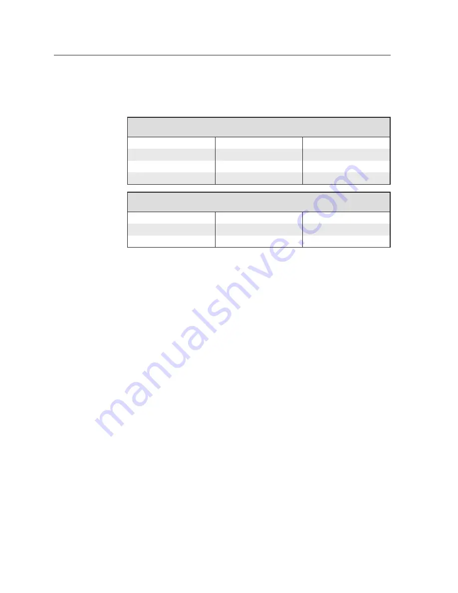
Default Buttons 

10 preinstalled buttons with the following labels

DISPLAY ON

DISPLAY OFF

MUTE

VOLUME 

<


VOLUME 

>


LAPTOP

PC

DVD

DOC CAM

AUXILIARY

Primary Buttons Accessory Kit

Contains 6 buttons with the following labels

MAC

VIDEO

BLU-RAY

SATELLITE

SOURCES

AUTO IMAGE

Additionally, Extron offers single buttons with various labels.  Check the Extron 

web-site at 

www.extron.com

 for a full list of available titles.

Содержание 60-1017-0200

Страница 1: ...TLP 350CV Cable Cubby TouchLink Panel Control Systems 68 1692 01 Rev A 12 09 ...

Страница 2: ...enden sollten Sie alle Sicherheits und Bedienungsanleitungen genau durchlesen und verstehen Aufbewahren der Anleitungen Die Hinweise zur elektrischen Sicherheit des Produktes sollten Sie aufbewahren damit Sie im Bedarfsfall darauf zurückgreifen können Befolgen der Warnhinweise Befolgen Sie alle Warnhinweise und Anleitungen auf dem Gerät oder in der Benutzerdokumentation Keine Zusatzgeräte Verwende...

Страница 3: ...n a commercial environment This equipment generates uses and can radiate radio frequency energy and if not installed and used in accordance with the instruction manual may cause harmful interference to radio communications Operation of this equipment in a residential area is likely to cause harmful interference in which case the user will be required to correct the interference at his own expense ...

Страница 4: ......

Страница 5: ...s and AAPs 2 6 Install the Included Power Module 2 6 AAP Assembly 2 7 Install Pass through AAP Cables 2 8 Installing Passive AAPs 2 9 Installing the Shelf Assembly 2 10 Mounting the TLP 350CV 2 11 Mounting the Power Supply US models only 2 12 Furniture Mounting 2 12 Using the ZipClip 100 2 13 Attaching removing the clip and power supply 2 13 Using tie wraps for cable strain relief 2 13 Connecting ...

Страница 6: ...oftware 4 1 Software Control 4 2 Installing Software 4 2 System requirements 4 2 GUI Configurator and Global Configurator installation 4 3 Updating Firmware 4 4 GUI Configurator 4 5 Global Configurator 4 9 Appendix A Specifications Part Numbers and Accessories A 1 Specifications A 2 Part Numbers Included parts A 5 Pass through and Blank AAPs A 5 AAP Brackets A 5 Accessories Optional A 6 Appendix B...

Страница 7: ...TLP 350CV 1 Chapter One Introduction About This Manual About the TLP 350CV Features Requirements ...

Страница 8: ... controlled monitored and accessed when connected to a Local Area Network Wide Area Network or the Internet A V connectivity and cable management is provided by convenient pullout cables such as VGA 3 5 mm audio A V network HDMI DVI and Display port cables Passive AAP plates and a dual AC outlet are also available Using the video input the panel can monitor video source devices whether as a previe...

Страница 9: ...es the screen the panel is reactivated Trim Ring and lid are available in black anodized or brushed aluminium to match room decor Video source monitoring for use as a preview confidence monitor or security camera monitor to provide a visual full motion sample of any composite or S video source Extron RGB 580xi Interface Extron IPL 250 IP Link Ethernet Control Processor SOG SERR DDSP V SYNC WIDTH N...

Страница 10: ...recommended for running GUI Configurator or Global Configurator 3 Operating System Microsoft Windows XP CPU Intel 1 2 GHz or compatible processor Memory 1 GB of RAM Hard Disk space 100 MB including 280 MB for the NET 2 0 Framework Screen Resolution 1024 x 768 resolution at 32 bit color Network Connection 100 Mbps Windows compatible mouse or other pointing device Control Interface An Extron IP Link...

Страница 11: ...ion Overview Obtain Cutout Dimensions Preparing the Table Cutting the Table Preparing the Routing Template Installing the Cables and AAPs Mounting the TLP 350CV Power Supply Installation US Models Only Connecting the TLP 350CV Front Panel Controls and Indicators ...

Страница 12: ...l conduit install an Extron flexible conduit kit Refer to the Flexible Conduit Kit Installation Guide Extron part 68 734 01 See Install the Included Power Module on page 2 6 6 Install cables into the cable pass through AAPs and loosely fasten to the AAP Shelf See Installing Pass through AAP cable on page 2 8 7 If applicable install passive AAPs and loosely fasten to the AAP shelf Connect cables to...

Страница 13: ...ess side is oriented as desired Preparing the Table A hand router using the routing template or a CNC wood router are the most accurate preferred and recommended methods for preparing the table for the TLP 350CV After verifying and checking dimensions prepare required templates based on the method of cut C The opening in the table for the Cable Cubby should be cut only by licensed and bonded craft...

Страница 14: ...e from Extron for the Cable Cubby products See TLP 350CV Routing Template in the Accessories list in Appendix A for part numbers Extron recommends using this template as a guide to cut the hole in the table where the TLP 350CV will be installed 1 Cut 1 2 inch x 4 inch strips of soft finished lumber at least long enough to span the distance between the desired installation location on the mounting ...

Страница 15: ...ntered on the mounting location Angle the template for the optimum positioning If necessary use a square to ensure the template is properly positioned Extron is not responsible for an improperly positioned Cable Cubby 3 Once the template assembly is positioned properly secure the assembly to the table with C clamps W Wear safety glasses when operating the router Failure to comply can result in eye...

Страница 16: ...e if used must be installed first and takes two or three AAP spaces depending upon the module Install the Included Power Module From the underside of the Cable Cubby gently push the power module into position at the desired location and elevation Secure the power module into position with two 4 40 Phillips head screws N The included power module takes up two or three AAP spaces and will be install...

Страница 17: ...ss through AAPs COM PUTER A U D IO Figure 2 4 Shelf brackets with pass through AAPs shown on right and passive AAPs on left The easiest way to install the cables and AAPs is to populate the shelf brackets with pass through and or passive AAP plates outside the Cubby as shown then install the populated AAP shelf assembly into the enclosure ...

Страница 18: ...les can run individually in separate channels or be combined allowing two cables to run in the channel Generally it is best to run one cable per channel Match the diameter of the cables to the channel opening The combined cable diameters should still allow the cables to be freely pulled from the Cable Cubby and easily returned Figure 2 5 Cable pass through AAPs Install cables in the channels as fo...

Страница 19: ...7 Pass through cable installation 4 Press the cable s into the desired opening 5 Continue in the same manner until all pass through AAPs are installed Installing Passive AAPs The split or blank AAPs may be replaced with passive Extron AAPs shown in figure 2 4 Passive AAPs allow direct cable connection using terminated cables Replace a set of split AAPs as follows N It may be easier to cable the re...

Страница 20: ...g nuts Retighten the AAP mounting nuts once the AAP shelf assembly is installed in position COM PUTER A U D IO Philips Head Screws secures AAP Shelf Assembly Tighten down AAP Nuts Push assembly through bottom of enclosure Large holes provide tool access to fasten rear brackets 2 1 3 Figure 2 8 AAP shelf assembly installation 2 With the AAP assembly at the desired location install two Phillips head...

Страница 21: ...eding the cables hanging from the underside of the enclosure carefully lower the Cable Cubby enclosure into the cutout to test the fit If necessary remove the enclosure and use a file or rasp to enlarge or smooth the edges of the opening figure 2 9 Table Clamp Both Sides PC LAP TO P DV D DO C CA M AU XIL IAR Y DIS PLA Y ON DIS PLA Y OF F AU TO IMA GE VO LUM E VO LUM E Extron Figure 2 9 Cable Cubby...

Страница 22: ... the way Power LED ZipClip Mounting Slots Notches for Securing Tie Wrap Figure 2 10 ZipClip power supply Furniture Mounting Begin by mounting the ZipClip 100 bracket 1 Attach the ZipClip to the mounting surface using two or more screws as shown Make sure the clip is oriented with the appropriate surface facing the mounting surface and with the tab accessible from the front of the furniture N Four ...

Страница 23: ...lace To remove the power supply from the ZipClip 1 Press the ZipClip tab 2 Pivot the power supply and lift it out of the ZipClip Using tie wraps for cable strain relief 1 Attach the power supply to the ZipClip 100 mounting clip 2 Fastening the power output cord to the ZipClip base a Insert tie wraps along the notches on the side of the power supply and through the ZipClip tie wrap anchor points th...

Страница 24: ...ly voids all regulatory compliance certification and may cause damage to the supply and the TLP 350CV POWER 12V 1 0A MAX LAN VID Y C PREVIEW INPUT Ground 12 VDC External Power Supply 12 VDC 1 A Orange Captive Screw Connector Tie Wrap Figure 2 14 Connect power supply C The power supply shall not be permanently fixed to the building structure or similar structures The power supply shall not be locat...

Страница 25: ...lue 4 blue 5 white blue 5 white blue 6 green 6 green 7 white brown 7 white brown 8 brown 8 brown Crossover Cable for direct connection to a PC End 1 End 2 Pin Wire Color Pin Wire Color 1 white orange 1 white green 2 orange 2 green 3 white green 3 white orange 4 blue 4 blue 5 white blue 5 white blue 6 green 6 orange 7 white brown 7 white brown 8 brown 8 brown Figure 2 15 Ethernet cable connector te...

Страница 26: ... dedicated customizable function buttons provide quick access to key functions A set of 6 buttons with alternative labels is included with the TLP 350CV There are also additional titles available See Appendix B Reset Modes and Button Replacement for available labels ordering instructions and a procedure for changing the buttons e Menu Button under faceplate A menu button is used to configure syste...

Страница 27: ...TLP 350CV 3 Chapter Three Initial Configuration Configuring the TLP 350CV Initial Setup Internal On screen Menus ...

Страница 28: ...Menu Allows adjustment of the Sleep Timer Panel Brightness Backlight Auto backlight operation and the LED Backlight Main Vol Time IP Exit Down Up Down On On Up Sleep timer 50000 Sec Backlight 073 Auto Backlight Vid LED Backlight Figure 3 2 Main menu Sleep Timer Sleep mode is activated when there has been a period 0 to 50000 seconds of inactivity The backlight is switched off and the touch screen g...

Страница 29: ...s the user to adjust the maximum volume of the sound individual volume of button click feedback and audio playback Main Down Up Down Up Down Up Master 255 Click 255 Sounds 255 Figure 3 3 Volume control menu Master Volume The Master Volume defines the maximum volume for all playback All other volume settings will be scaled in proportion If the master volume is set at 50 of full volume and the Click...

Страница 30: ...17 Minutes 30 Figure 3 4 Time menu IP Network The IP configuration menu displays network related parameters Main 192 168 254 254 MAC 00 05 A6 05 7D A6 Off 255 255 000 000 IP Address DHCP Subnet Mask Figure 3 5 IP menu IP Address This text box displays the currently configured IP address for the panel To change the IP address 1 Press the on screen IP address box A new screen appears with a number p...

Страница 31: ...ggles DHCP Off and On Generally the TLP 350CV should be assigned a static IP to avoid communications errors on local networks Video The video menu adjusts the appearance of a video signal connected to the video inputs Main Down Up Down Up Down Up Down Up Contrast 063 Bright 127 Color 064 Tint 129 Figure 3 6 Video adjustments menu Use the Down and Up buttons to adjust contrast between 0 and 127 def...

Страница 32: ...ond to access the calibration menu The screen shown on the right appears 2 Using a finger press and hold on the green box until the color reverts to gray with a white border and a second box is highlighted in green 3 Move to the newly highlighted box and repeat step 2 4 Repeat until all four boxes have been pressed and are gray 5 Once all four boxes have been calibrated the screen automatically re...

Страница 33: ...TLP 350CV 4 Chapter Four Configuration Software Software Control Installing Software Updating Firmware GUI Configurator Global Configurator ...

Страница 34: ... control functions to buttons and other items in the layout GUI Configurator offers several templates designed to manage control system devices Once a template is loaded into the application customize and configure it to meet the needs of a specific A V system These two programs provide versatility and adaptability for configuration and control of an A V system as it grows and evolves Installing S...

Страница 35: ...structions N GUI Configurator requires Global Configurator version 3 0 or higher By default the Installer program creates a C Program Files Extron Globalapplication name folder containing the Global Configurator program An icon may also be placed on the Windows desktop Both programs are also available for free download from the Extron Web site at www extron com GUI Configurator web listing top Glo...

Страница 36: ...dure as for installing the GUI Configurator and Global Configurator programs see page 4 2 To install from the Extron Web site select the Download tab and click on the Software tab locate the Firmware Loader and click Download Follow the onscreen instructions to complete installation 3 From the same site download the firmware for the TLP 350CV Click on the Download tab on the Extron home page and s...

Страница 37: ...ons specific to controlling the selected type of audio equipment For the TLP 350CV 10 function buttons to the side of the screen are also available to control objects GUI Configurator offers several templates designed to manage control system devices Once a template is loaded into the application it can be customized and configured to meet the needs of a specific A V system This section provides a...

Страница 38: ...creen 2 Use the GUI Configurator Start Options dialog box to select from Start New Project Open an Existing Project Download an Existing Project from a Panel Check the Do not show this dialog again box to disable the start options opening screen if desired Figure 4 8 GUI Configurator start options 3 Decide whether you want to Open a new project without a template a Choose Start a New Project or fr...

Страница 39: ...older and click OK g In the After Download section enable or disable the option to open the project when the download completes h Click OK 4 The initial screen is divided into a series of panes offering a range of tools that can be used to design or modify the project For full details on how to use these tools consult the Help file in the Help Menu click on Contents or press the F1 key while withi...

Страница 40: ...menu select Upload All to Panels The Build Manager dialog box opens showing the build progress Once the build is complete this dialog box closes and the File Upload Manager screen opens The upload begins automatically b Select the Close this dialog when upload completes checkbox in the Automatic Settings section so the File Upload Manager screen closes automatically once the upload completes This ...

Страница 41: ...that have Ethernet ports for network connectivity and serial infrared IR ports for A V device connectivity See page 1 4 for a list of IP Link devices A V devices video projectors displays DVD players VCRs document cameras projector screens and room lighting These devices are the equipment used to generate and display an audio visual presentation Once this global configuration file is built GC gene...

Страница 42: ...nk product will be similar but always consult the Global configurator Help File for exact information about the product being used 1 Click on the GC3 desk top icon The program opens at the main screen and a Start Options dialog box Create a New Project Open An Existing Project View Global Conf Import Project Co Do not show this dialog again OK Exit Add Driver Subscriptions Select Start Option Glob...

Страница 43: ...click on the Advanced button The button name will change to Basic as shown in the figure above a Select the IP Link Device from the drop down menu In this example an IPL 250 controller is added Adding a different IP Link product will be similar b Enter the IP address of the IP Link controller The default value is 192 168 254 254 but this may have been changed Check with your IT Department to verif...

Страница 44: ...vailable ports Figure 4 14 GUI Configurator available ports 6 Click on Touch Panel Port 1 The screen changes to show options available for the TouchPanel To add the screen that was designed in GUI Configurator and uploaded to the TouchPanel unit click on Click here to add one Figure 4 15 GUI Configurator add port ...

Страница 45: ...c Set the Telnet Port usually 23 d If necessary enter the password e Check the Import Apply Layout box f Click OK Model TCP Name IP Address Display Name Telnet Port Admin Password Auto Configure IP Address MAC Address Import Apply Layout Cancel OK Basic TLP 350CV 192 168 254 255 TLP 350CV 192 168 254 255 23 Add Touch Panel a b c d f e Figure 4 16 GUI Configurator Add touch panel dialog ...

Страница 46: ... the GUI from the TouchLink panel TLP 350CV 192 168 254 255 Touch Panel Port 2 Touch Panel Ports IPL 250 192 168 254 254 Figure 4 17 GUI Configurator Touch panel imported 9 For complete instructions on how to assign functions to the buttons on the screen see the Global Configurator Help File ...

Страница 47: ...TLP 350CV A Appendix A Specifications Part Numbers and Accessories Specifications Included Parts Accessories Optional ...

Страница 48: ...plex with autodetect Ethernet protocol ICMP IP TCP control UDP DHCP Telnet Default settings Link speed and duplex level autodetected IP address 192 168 254 254 Subnet mask 255 255 0 0 Default gateway 0 0 0 0 DHCP off Program control Extron Global Configurator 3 0 or higher GUI Configurator for Windows Extron Simple Instruction Set SIS Microsoft Internet Explorer ver 6 or higher Telnet Control touc...

Страница 49: ...F 0 to 50 C 10 to 90 noncondensing Cooling Convection no vents Mounting Furniture mount With included hardware Min max table thickness 0 375 to 2 00 0 95 cm to 5 08 cm Enclosure type Metal Dimensions diagram examples FRONT VIEW TLP 350CV BOTTOM VIEW TOP VIEW RIGHT SIDE VIEW LEFT SIDE VIEW N Architectural Adapter Plates AAPs shown in the diagrams above and in photographs are examples only AAPs are ...

Страница 50: ...e cutout inside rim 7 50 0 00 0 02 W x 6 00 0 00 0 02 D 19 05 0 00 0 05 cm W x 15 24 0 00 0 05 cm D Box under surface 7 42 H x 10 87 W front rear of unit x 5 64 D with clamps 18 85 cm H x 27 6 cm W x 14 32 cm D with clamps Product weight 5 8 lbs 2 6 kg Shipping weight 9 lbs 4 kg Vibration ISTA 1A in carton International Safe Transit Association Regulatory compliance Safety CE c UL UL EMI EMC CE C ...

Страница 51: ...lack anodized no AC outlet TLP 350CV Brushed aluminum no AC outlet 60 1017 020A 60 1017 021A 60 1017 020D 60 1017 021D 60 1017 020J 60 1017 021J 60 1017 0200 60 1017 0210 Default Button kit 10 preinstalled Power Supply 12 VDC 1 0 A Button Kit Accessories Table Clamp assembly 2 AAP nuts bag DVD with software and manual TLP 350CV Setup Guide Pass through and Blank AAPs AAPs Pass through Blank US 4 3...

Страница 52: ...tron com German French Button Kit 70 698 07 Cable Retractor VGA Cable Retractor PC Audio Cable Retractor Network Cable Retractor HDMI Cable Retractor USB Cable Retractor DVI 70 678 01 70 678 02 70 678 03 70 678 04 70 678 05 70 678 06 IPL T S1 60 801 81 IPL T S2 60 544 81 IPL T S4 60 544 83 IPL T S6 60 544 84 IPL 250 60 1026 81 IPL T CR 48 60 544 05 IPL T SFI 244 60 544 06 Single space AAP Bracket ...

Страница 53: ...TLP 350CV B Appendix B Reset Modes and Button Replacement Reset Modes Button Kit Contents Button Replacement ...

Страница 54: ...ng a paper clip push through the reset access hole on the right side of the faceplate as shown below N The access holes are very small Take care when pressing the reset button to avoid scratching the faceplate The successful completion of a reset is indicated by four flashes of the reset LED The TLP 350CV has four reset modes that can be initiated by pressing the Reset button on the Front Panel Se...

Страница 55: ...nd Mode 3 toggles events on or off Useful for troubleshooting Reset all IP Settings 4 Press and hold the Reset button for about 6 sec until the Power LED blinks twice once at 3 sec again at 6 sec then release and within 1 second press Reset momentarily 1 sec N Nothing happens if the momentary press does not occur within 1 second Mode 4 Enables ARP capability Set the IP address to default Sets the ...

Страница 56: ...included button accessory kit offers several alternate titles Default Buttons 10 preinstalled buttons with the following labels DISPLAY ON DISPLAY OFF MUTE VOLUME VOLUME LAPTOP PC DVD DOC CAM AUXILIARY Primary Buttons Accessory Kit Contains 6 buttons with the following labels MAC VIDEO BLU RAY SATELLITE SOURCES AUTO IMAGE Additionally Extron offers single buttons with various labels Check the Extr...

Страница 57: ...uttons from falling out of the faceplate 4 Replace all desired buttons making certain the text has the proper orientation 5 The buttons easily fall from the faceplate when it is tilted past vertical If the touch panel was not rotated prior to this rotate it towards the front of the enclosure to a 30 angle now 6 Replace the faceplate from the top First slide the bottom into the recessed space on th...

Страница 58: ...Reset Modes and Button Replacement cont d TLP 350CV Reset Modes and Button Replacement B 6 ...

Страница 59: ...ne F12 PO Box 293666 United Arab Emirates Dubai This Limited Warranty does not apply if the fault has been caused by misuse improper handling care electrical or mechanical abuse abnormal operating conditions or non Extron authorized modification to the product If it has been determined that the product is defective please call Extron and ask for an Applications Engineer at 714 491 1500 USA 31 33 4...

Страница 60: ...USA Canada Only 1 919 863 1794 1 919 863 1797 FAX Extron Europe 800 3987 6673 Inside Europe Only 31 33 453 4040 31 33 453 4050 FAX Extron Asia 800 7339 8766 Inside Asia Only 65 6383 4400 65 6383 4664 FAX Extron Japan 81 3 3511 7655 81 3 3511 7656 FAX Extron China 400 883 1568 Inside China Only 86 21 3760 1568 86 21 3760 1566 FAX Extron Middle East 971 4 2991800 971 4 2991880 FAX ...

Отзывы: