SINUS PENTA
REGENERATIVE
APPLICATION
129/
140
0
1
2
3
4
3.15.
RESISTOR BRAKING MENU
3.15.1.
O
VERVIEW
A braking resistor connected between power terminals 47+ and 48 B of the regenerative drive can be used
for the RGN drive sizes provided with a built-in braking unit (up to size S30 included). The braking resistor is
used only when regeneration can cause overvoltage faults in the regenerative drive.
This menu allows setting the max. duty-cycle of the drive braking resistor.
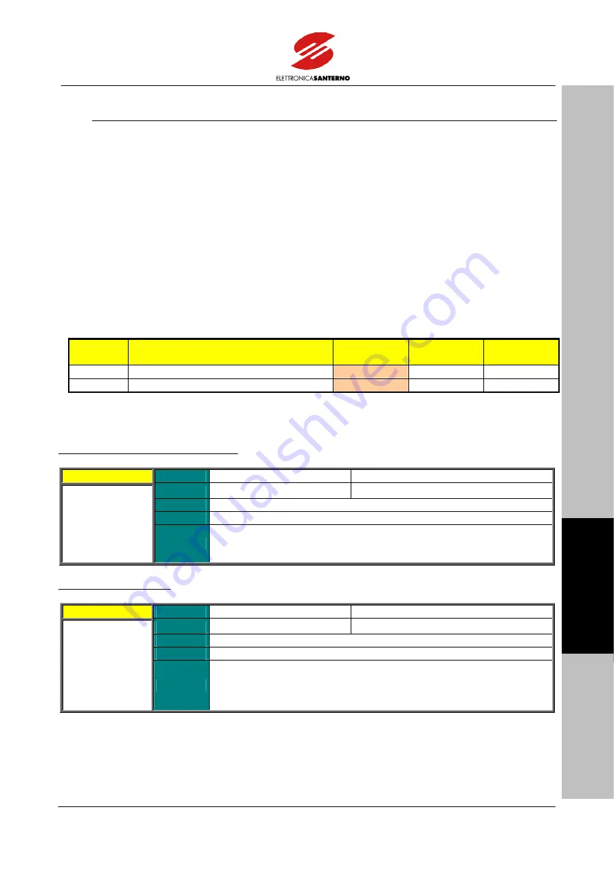
The maximum allowable duty-cycle of the braking resistor is set through parameters C211 [Max. Continuous
Operation Time (Ton)] and C212 [Max. Duty- cycle (100 * Ton / (Ton+Toff) [%] )]. If Ton = C212, when the
time set is over, the respective command is disabled for a time equal to Toff = (100 – C211) * C212 / C211
[sec].
3.15.2.
L
IST OF
P
ROGRAMMABLE
P
ARAMETERS
C211
AND
C212
Parameter
FUNCTION
User Level
MODBUS
Address
DEFAULT
VALUES
C211
Max. Continuous Operation Time
ENGINEERING
1211 2000
sec
C212
Braking Duty-cycle
ENGINEERING
1212 10%
Table 23: List of parameters C211 and C212.
C211 Max. Continuous Operation Time
C211
Range
0 ÷ 32000
0 ÷ 32000 msec
Default
2000
2000 sec
Level
ENGINEERING
Address
1211
Function
This parameter sets the max. continuous operation time for the braking
resistor. If the braking resistor is used for the time set in C211, the relevant
command is disabled for the rest time set in C212.
C212 Braking Duty-cycle
C212
Range
0 ÷ 100
0 ÷ 100 %
Default
10
10%
Level
ENGINEERING
Address
1212
Function
C212 = (Ton/(Ton+Toff))*100
This parameter sets the allowable duty-cycle for the braking resistor. It is
expressed as a percentage and sets the rest time of the braking resistor
after its max. continuous operation time set in C211.


