


Protections
92
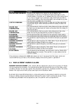
Display
Reason
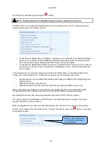
PROTECTIONS DISABLED
Shutdown and electrical trip alarms can be disabled by user
configuration. In this case, Protections Disabled will appear on the
module display; The alarm text is displayed but the engine will continue
to run. This is ‘logged’ by the module to allow DSE Technical Staff to
check if the protections have been disabled on the module at any time.
This feature is available from V4 onwards.
LOW OIL PRESSURE
The module detects that the engine oil pressure has fallen below the
low oil pressure pre-alarm setting level after the
Safety On
timer has
expired.
ENGINE HIGH
TEMPERATURE
The module detects that the engine coolant temperature has exceeded
the high engine temperature pre-alarm setting level after the
Safety On
timer has expired.
ENGINE LOW
TEMPERATURE
The module detects that the engine coolant temperature has fallen
below the high engine temperature pre-alarm setting level.
OVERSPEED
The engine speed has risen above the overspeed pre alarm setting
UNDERSPEED
The engine speed has fallen below the underspeed pre alarm setting
GENERATOR OVER
FREQUENCY
The generator output frequency has risen above the pre-set pre-alarm
setting.
GENERATOR UNDER
FREQUENCY
The generator output frequency has fallen below the pre-set pre-alarm
setting after the
Safety On
timer has expired.
GENERATOR OVER
VOLTAGE
The generator output voltage has risen above the pre-set pre-alarm
setting.
GENERATOR UNDER
VOLTAGE
The generator output voltage has fallen below the pre-set pre-alarm
setting after the
Safety On
timer has expired.
ECU WARNING
The engine ECU has detected a warning alarm and has informed the
DSE module of this situation. The exact error is also indicated on the
module’s display.
If the module is configured for,
CAN
and receives an “error” message from the engine control unit,
‘Can ECU Warning” is shown on the module’s display and a warning alarm is generated.
8.4 HIGH CURRENT WARNING ALARM
GENERATOR HIGH CURRENT,
if the module detects a generator output current in excess of the pre-
set trip a warning alarm initiates. The module shows Alarm Warning High Current. If this high current
condition continues for an excess period, then the alarm escalates to a shutdown condition. For further
details of the high current alarm, please see High Current Shutdown Alarm.
By default, High Current Warning Alarm is self-resetting when the overcurrent condition is removed.
However enabling ‘all warnings are latched’ will cause the alarm to latch until reset manually. This is
enabled using the 8600 series configuration suite in conjunction with a compatible PC.
Содержание DSE8610
Страница 47: ...Installation 47 4 2 2 3 PHASE 4 WIRE WITHOUT EARTH FAULT PROTECTION...
Страница 51: ...Installation 51 4 3 2 SINGLE PHASE WITHOUT EARTH FAULT...
Страница 53: ...Installation 53 4 3 4 2 PHASE L1 L2 3 WIRE WITHOUT EARTH FAULT...
Страница 55: ...Installation 55 4 3 6 2 PHASE L1 L3 3 WIRE WITHOUT EARTH FAULT MEASURING...
Страница 100: ...Protections 100 8 8 1 EARTH FAULT TRIPPING CURVES NOTE DSE Factory setting is time multiplier K 0 4...
Страница 118: ...Intentionally Left Blank 118...


