


Specifications
12
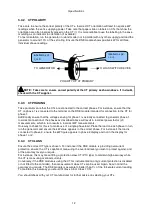
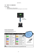
3.4.2 CT POLARITY
Take care to ensure the correct polarity of the CTs. Incorrect CT orientation will lead to negative kW
readings when the set is supplying power. Take note that paper stick-on labels on CTs that show the
orientation are often incorrectly placed on the CT (!). It is more reliable to use the labelling in the case
moulding as an indicator to orientation (if available).
To test orientation, run the generator in island mode (not in parallel with any other supply) and load the
generator to around 10% of the set rating. Ensure the DSE module shows positive kW for all three
individual phase readings.
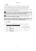
TO GENERATOR
TO LOAD SWITCH DEVICE
POLARITY OF CT PRIMARY
NOTE: Take care to ensure correct polarity of the CT primary as shown above. If in doubt,
check with the CT supplier.
3.4.3 CT PHASING
Take particular care that the CTs are connected to the correct phases. For instance, ensure that the
CT on phase 1 is connected to the terminal on the DSE module intended for connection to the CT for
phase 1.
Additionally ensure that the voltage sensing for phase 1 is actually connected to generator phase 1.
Incorrect connection of the phases as described above will result in incorrect power factor (pf)
measurements, which in turn results in incorrect kW measurements.
One way to check for this is to make use of a single-phase load. Place the load on each phase in turn,
run the generator and ensure the kW value appears in the correct phase. For instance if the load is
connected to phase 3, ensure the kW figure appears in phase 3 display and not in the display for
phase 1 or 2.
3.4.4 CT CLASS
Ensure the correct CT type is chosen. For instance if the DSE module is providing overcurrent
protection, ensure the CT is capable of measuring the overload level you wish to protect against, and
at the accuracy level you require.
For instance, this may mean fitting a protection class CT (P10 type) to maintain high accuracy while
the CT is measuring overload currents.
Conversely, if the DSE module is using the CT for instrumentation only (current protection is disabled
or not fitted to the controller), then measurement class CTs can be used. Again, bear in mind the
accuracy you require. The DSE module is accurate to better than 1% of the full-scale current reading.
To maintain this accuracy you should fit Class 0.5 or Class 1 CTs.
You should check with your CT manufacturer for further advice on selecting your CTs
labelled as p1,
k
or K
labelled as p2,
l
or L
Содержание DSE8610
Страница 47: ...Installation 47 4 2 2 3 PHASE 4 WIRE WITHOUT EARTH FAULT PROTECTION...
Страница 51: ...Installation 51 4 3 2 SINGLE PHASE WITHOUT EARTH FAULT...
Страница 53: ...Installation 53 4 3 4 2 PHASE L1 L2 3 WIRE WITHOUT EARTH FAULT...
Страница 55: ...Installation 55 4 3 6 2 PHASE L1 L3 3 WIRE WITHOUT EARTH FAULT MEASURING...
Страница 100: ...Protections 100 8 8 1 EARTH FAULT TRIPPING CURVES NOTE DSE Factory setting is time multiplier K 0 4...
Страница 118: ...Intentionally Left Blank 118...


