


Specifications
18
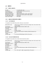
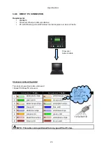
3.7 COMMUNICATION PORTS
USB Port
USB2.0 Device for connection to PC running DSE configuration
suite only
Max distance 6m (yards)
Serial Communication
RS232 and RS485 are both fitted and provide independent
operation
RS232 Serial port
Non – Isolated port
Max Baud rate 115.2K baud subject to S/W
TX, RX, RTS, CTS, DSR, DTR, DCD
Male 9 way D type connector
Max distance 15m (50 feet)
RS485 Serial port
Isolated
Data connection 2 wire + common
Half Duplex
Data direction control for Transmit (by s/w protocol)
Max Baud Rate 115200
External termination required (120
Ω
)
Max common mode offset 70V (on board protection transorb)
Max distance 1.2km (¾ mile)
MSC Multi Set Communication
Port
Multi Set Communication Port (connection to other DSE
modules)
Data connection 2 wire + common
Issolated
External termination required (120
Ω
)
Max common mode offset 70V (on board protection transorb)
Max distance 250M using Belden 9841 Cable or equivalent
CAN Port
Engine CAN Port
Standard implementation of ‘Slow mode’, up to 250K bits/s
Non-Isolated.
Internal Termination provided (120
Ω
)
Max distance 40m (133 feet)
NOTE: For additional length, the DSE124 CAN
Extender is available. Please refer to DSE Publication:
057-116 DSE124 Operator Manual for more information.
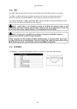
Ethernet
Auto detecting 10/100 Ethernet port.
3.8 COMMUNICATION PORT USAGE
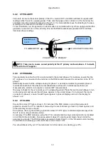
3.8.1 CAN INTERFACE
Modules are fitted with the CAN interface as standard and are capable of
receiving engine data from engine CAN controllers compliant with the
CAN standard.
CAN enabled engine controllers monitor the engine’s operating
parameters such as engine speed, oil pressure, engine temperature
(among others) in order to closely monitor and control the engine. The industry standard
communications interface (CAN) transports data gathered by the engine controller interface. This
allows generator controllers such as the DSE8600 series to access these engine parameters with no
physical connection to the sensor device.
NOTE: For further details for connections to CAN enabled engines and the functions
available with each engine type, refer to the manual
Electronic Engines and DSE Wiring.
Part
No. 057-004
Содержание DSE8610
Страница 47: ...Installation 47 4 2 2 3 PHASE 4 WIRE WITHOUT EARTH FAULT PROTECTION...
Страница 51: ...Installation 51 4 3 2 SINGLE PHASE WITHOUT EARTH FAULT...
Страница 53: ...Installation 53 4 3 4 2 PHASE L1 L2 3 WIRE WITHOUT EARTH FAULT...
Страница 55: ...Installation 55 4 3 6 2 PHASE L1 L3 3 WIRE WITHOUT EARTH FAULT MEASURING...
Страница 100: ...Protections 100 8 8 1 EARTH FAULT TRIPPING CURVES NOTE DSE Factory setting is time multiplier K 0 4...
Страница 118: ...Intentionally Left Blank 118...


