


Specifications
11
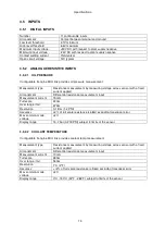
3.4 GENERATOR CURRENT SENSING
Measurement type
True RMS conversion
Sample Rate
5KHz or better
Harmonics
Up to 10
th
or better
Nominal CT secondary rating
1A or 5A (5A recommended)
Maximum continuous current
5A
Overload Measurement
3 x Nominal Range setting
Absolute maximum overload
50A for 1 second
Burden
0.5VA (0.02
Ω
current shunts)
common mode offset
±2V peak plant ground to CT common terminal
Resolution
0.5% of 5A
Accuracy
±1% of Nominal (1A or 5A) (excluding CT error)
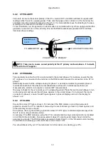
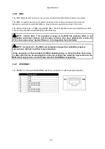
3.4.1 VA RATING OF THE CTS
The VA burden of the DSE8610 module on the CTs is 0.5VA. However depending upon the type and
length of cabling between the CTs and the DSE8610 module, CTs with a greater VA rating than the
module are required.
The distance between the CTs and the
measuring module should be
estimated and cross-referenced
against the chart opposite to find the
VA burden of the cable itself.
If the CTs are fitted within the
alternator top box, the star point
(common) of the CTs should be
connected to system ground (earth) as
close as possible to the CTs. This
minimises the length of cable used to
connect the CTs to the DSE module.
Example.
If 1.5mm² cable is used and the
distance from the CT to the measuring
module is 20m, then the burden of the
cable alone is approximately 15VA. As
the burden of the DSE controller is
0.5VA, then a CT with a rating of at
least 15+0.5V = 15.5VA must be used.
If 2.5mm² cables are used over the
same distance of 20m, then the
burden of the cable on the CT is
approximately 7VA. CT’s required in
this instance is at least 7.5VA (7+0.5).
NOTE: Details for 4mm² cables are shown for reference only. The connectors on the DSE
modules are only suitable for cables up to 2.5mm².
NOTE: CTs with 5A secondary windings are recommended with DSE modules. 1A CTs can
be used if necessary however, the resolution of the readings is 5 times better when using 5A
CTs.
Содержание DSE8610
Страница 47: ...Installation 47 4 2 2 3 PHASE 4 WIRE WITHOUT EARTH FAULT PROTECTION...
Страница 51: ...Installation 51 4 3 2 SINGLE PHASE WITHOUT EARTH FAULT...
Страница 53: ...Installation 53 4 3 4 2 PHASE L1 L2 3 WIRE WITHOUT EARTH FAULT...
Страница 55: ...Installation 55 4 3 6 2 PHASE L1 L3 3 WIRE WITHOUT EARTH FAULT MEASURING...
Страница 100: ...Protections 100 8 8 1 EARTH FAULT TRIPPING CURVES NOTE DSE Factory setting is time multiplier K 0 4...
Страница 118: ...Intentionally Left Blank 118...


