


Description Of Controls
67
In case of communication failure between the modem and DSE8600 series module, the modem is
automatically reset and initialisation is attempted once more:
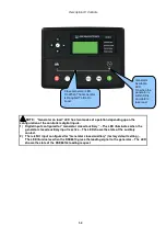
3)
In the case of a module that is unable to communicate with the modem, the display will
continuously cycle between ‘Modem Reset’ and ‘Modem Initialising’ as the module resets the
modem and attempts to communicate with it again, this will continue until correct
communication is established with the modem.
In this instance, you should check connections and verify the modem operation.
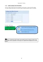
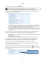
Example 2 – Module connected to a modem.
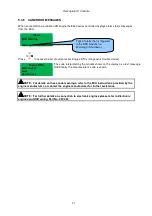
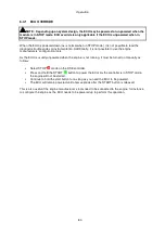
Example 3 – Modem status of a GSM modem
Many GSM modems are fitted with a status LED to show operator cell status and ringing indicator.
These can be a useful troubleshooting tool.
In the case of GSM connection problems, try calling the DATA number of the SIMCARD with an
ordinary telephone. There should be two rings, followed by the modem answering the call and then
‘squealing’. If this does not happen, you should check all modem connections and double check with
the SIM provider that it is a DATA SIM and can operate as a data modem. DATA is NOT the same as
FAX or GPRS and is often called Circuit Switched Data (CSD) by the SIM provider.
NOTE: In the case of GSM modems, it is important that a DATA ENABLED SIM is used.
This is often a different number than the ‘voice number’ and is often called Circuit Switched
Data (CSD) by the SIM provider.
If the GSM modem is not purchased from DSE, ensure that it has been correctly set to operate at
9600 baud. You may need to install a terminal program on your PC and consult your modem supplier
to do this. GSM modems purchased from DSE are already configured to work with the DSE86xx
series module.
Currently connected GSM
operator and signal strength.
Содержание DSE8610
Страница 47: ...Installation 47 4 2 2 3 PHASE 4 WIRE WITHOUT EARTH FAULT PROTECTION...
Страница 51: ...Installation 51 4 3 2 SINGLE PHASE WITHOUT EARTH FAULT...
Страница 53: ...Installation 53 4 3 4 2 PHASE L1 L2 3 WIRE WITHOUT EARTH FAULT...
Страница 55: ...Installation 55 4 3 6 2 PHASE L1 L3 3 WIRE WITHOUT EARTH FAULT MEASURING...
Страница 100: ...Protections 100 8 8 1 EARTH FAULT TRIPPING CURVES NOTE DSE Factory setting is time multiplier K 0 4...
Страница 118: ...Intentionally Left Blank 118...


