


E-DWT-10000-AF OPERATION AND MAINTENANCE MANUAL
© 2008 DH Instruments, a Fluke Company
Page 10
2.2
SITE REQUIREMENTS
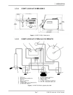
Install E-DWT-10000-AF on a flat, stable surface at a convenient height. If using the battery/charger
pack, consider its placement.
When used with its battery/charger pack, E-DWT-10000-AF requires no external support facilities. If not
using the battery, an electrical power source of 100 to 240VAC, 50-60 Hz is required.
2.3
SETUP
2.3.1
PREPARING FOR OPERATION
To prepare E-DWT-10000-AF for check out and operation:
Remove the protective plastic sheet from the front panel display.
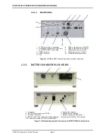
Familiarize yourself briefly with the E-DWT front and real panels and controls (see
Section
1.3.1
).
Connect the 12 VDC power supply pack to a source of 100 to 240V, 50-60 Hz AC power
and to the 12 VDC connection on the rear of the E-DWT; or, use the battery/charger pack
and cable if battery has been charged (see Section 3.3).
Connecting power causes the RPM4-E-DWT to power up.
Observe the front panel display as the RPM4-E-DWT initializes, error checks and goes to
the MAIN RUN screen (see Section 3.6.1). If the RPM4-E-DWT fails to reach the main
run screen, service is required. Record the sequence of operations and displays
observed and contact a
DHI
Authorized Service Provider (see Section 1, Table 25).
Check that one of the two green Valve Status LEDs on the front of the E-DWT is lit (the
red LED should NOT be ON). If neither of the green LEDs lights, check that the 12 pin
circular connector on the rear panel of the RPM4-E-DWT itself is properly connected to
the J1 ACC. connector.
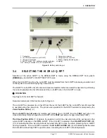
Install the four variable volume handles into the variable volume hub on the front of the E-DWT.
Leave the stainless steel plug in the top surface TEST port. Check that the gland holding
the plug is tight.
Check/Set Security Level
RPM4-E-DWT has a security system based on user levels. By default, the security
system is set to “low”, which includes access restriction to internal calibration coefficients,
and there is no password required to change the security level. See Section 3.9.5.5 for
information on the security level system. As part of the RPM4-E-DWT startup, determine
the security level that is appropriate for the RPM4-E-DWT and set a password if desired.
RPM4-E-DWT is delivered with the security level set to “low” to avoid inadvertent altering of
critical internal settings but with access to changing security levels unrestricted. It is recommended
that the low security level be maintained at all times and password protection be implemented if
control over setting of security levels is desired.
2.3.2
SETTING UP AUTOTEST FILES
E-DWT’s RPM4-E-DWT supports automated test/calibration sequences. AutoTest sequence
parameters for testing specific DUTs can be stored in File AutoTest files and recalled to run a
test. Consider setting up File AutoTest files for frequently tested DUTs as part of the E-DWT
set up process (see Section 3.1.3).
Содержание E-DWT-10000-AF
Страница 10: ...E DWT 10000 AF OPERATION AND MAINTENANCE MANUAL 2008 DH Instruments a Fluke Company Page VIII N NO OT TE ES S...
Страница 18: ...E DWT 10000 AF OPERATION AND MAINTENANCE MANUAL 2008 DH Instruments a Fluke Company Page 8 N NO OT TE ES S...
Страница 24: ...E DWT 10000 AF OPERATION AND MAINTENANCE MANUAL 2008 DH Instruments a Fluke Company Page 14 N NO OT TE ES S...
Страница 102: ...E DWT 10000 AF OPERATION AND MAINTENANCE MANUAL 2008 DH Instruments a Fluke Company Page 92 N NO OT TE ES S...
Страница 128: ...E DWT 10000 AF OPERATION AND MAINTENANCE MANUAL 2008 DH Instruments a Fluke Company Page 118 N NO OT TE ES S...
Страница 130: ...E DWT 10000 AF OPERATION AND MAINTENANCE MANUAL 2008 DH Instruments a Fluke Company Page 120 N NO OT TE ES S...
Страница 132: ...E DWT 10000 AF OPERATION AND MAINTENANCE MANUAL 2008 DH Instruments a Fluke Company Page 122 N NO OT TE ES S...


