[15] Preset
reference
on
Shifts between external reference and preset
reference. It is assumed that
[1] External/preset
has been selected in
parameter 3-04 Reference
Function
. Logic 0=external reference active;
logic 1=1 of the 8 preset references is active.
[16] Preset ref
bit 0
Preset ref. bits 0, 1, and 2 enable the selection
of 1 of the 8 preset references according to
.
[17] Preset ref
bit 1
Same as
[16] Preset ref bit 0
.
[18] Preset ref
bit 2
Same as
[16] Preset ref bit 0
.
Preset ref. bit
2
1
0
Preset ref. 0
0
0
0
Preset ref. 1
0
0
1
Preset ref. 2
0
1
0
Preset ref. 3
0
1
1
Preset ref. 4
1
0
0
Preset ref. 5
1
0
1
Preset ref. 6
1
1
0
Preset ref. 7
1
1
1
Table 4.3 Preset Ref. Bit
[19] Freeze
ref
Freezes the actual reference, which is now the
point of enable/condition for
[21] Speed up
and
[22]
Speed down
to be used. If
[21] Speed up
or
[22]
Speed down
is used, the speed change always
follows ramp 2 (
parameter 3-51 Ramp 2 Ramp Up
Time
and
parameter 3-52 Ramp 2 Ramp Down Time
)
in the range 0–
parameter 3-03 Maximum Reference
.
[20] Freeze
output
NOTICE
When
[20] Freeze output
is active, the
frequency converter cannot be stopped by
setting the signal on
[8] Start
to low. Stop
the frequency converter via a terminal
programmed for
[2] Coasting inverse
or
[3]
Coast and reset, inverse
.
Freezes the actual motor frequency (Hz), which is
now the point of enable/condition for
[21] Speed
up
and
[22] Speed down
to be used. If
[21] Speed up
or
[22] Speed down
is used, the speed change
always follows ramp 2 (
parameter 3-51 Ramp 2
Ramp Up Time
and
parameter 3-52 Ramp 2 Ramp
Down Time
) in the range 0–
parameter 1-23 Motor
Frequency
.
[21] Speed
up
Select
[21] Speed up
and
[22] Speed down
if digital
control of the up/down speed is needed (motor
potentiometer). Activate this function by selecting
either
[19] Freeze reference
or
[20] Freeze output
.
When speed up/down is activated for less than 400
ms, the resulting reference is increased/ decreased
by 0.1%. If speed up/down is activated for more
than 400 ms, the resulting reference follows the
setting in ramping up/down parameter 3-x1/ 3-x2.
Shut down
Catch up
Unchanged speed
0
0
Reduced by %-value
1
0
Increased by %-value
0
1
Reduced by %-value
1
1
Table 4.4 Shut Down/Catch Up
[22] Speed
down
Same as
[21] Speed up
.
[23] Set-up
select
bit 0
Select
[23] Set-up select bit 0
or
[1] Set-up select bit
1
to select 1 of the 2 set-ups. Set
parameter 0-10 Active Set-up
to
[9] Multi Set-up
.
[24] Set-up
select
bit 1
Default digital input 32. Same as
[23] Set-up select
bit 0
.
[26] Precise
stop inv.
Precise stop inverse function is available for
terminals 18 or 19.
[28] Catch up Increases reference value by percentage (relative)
set in
parameter 3-12 Catch up/slow Down Value
.
[29] Slow
down
Reduces reference value by percentage (relative)
set in
parameter 3-12 Catch up/slow Down Value
.
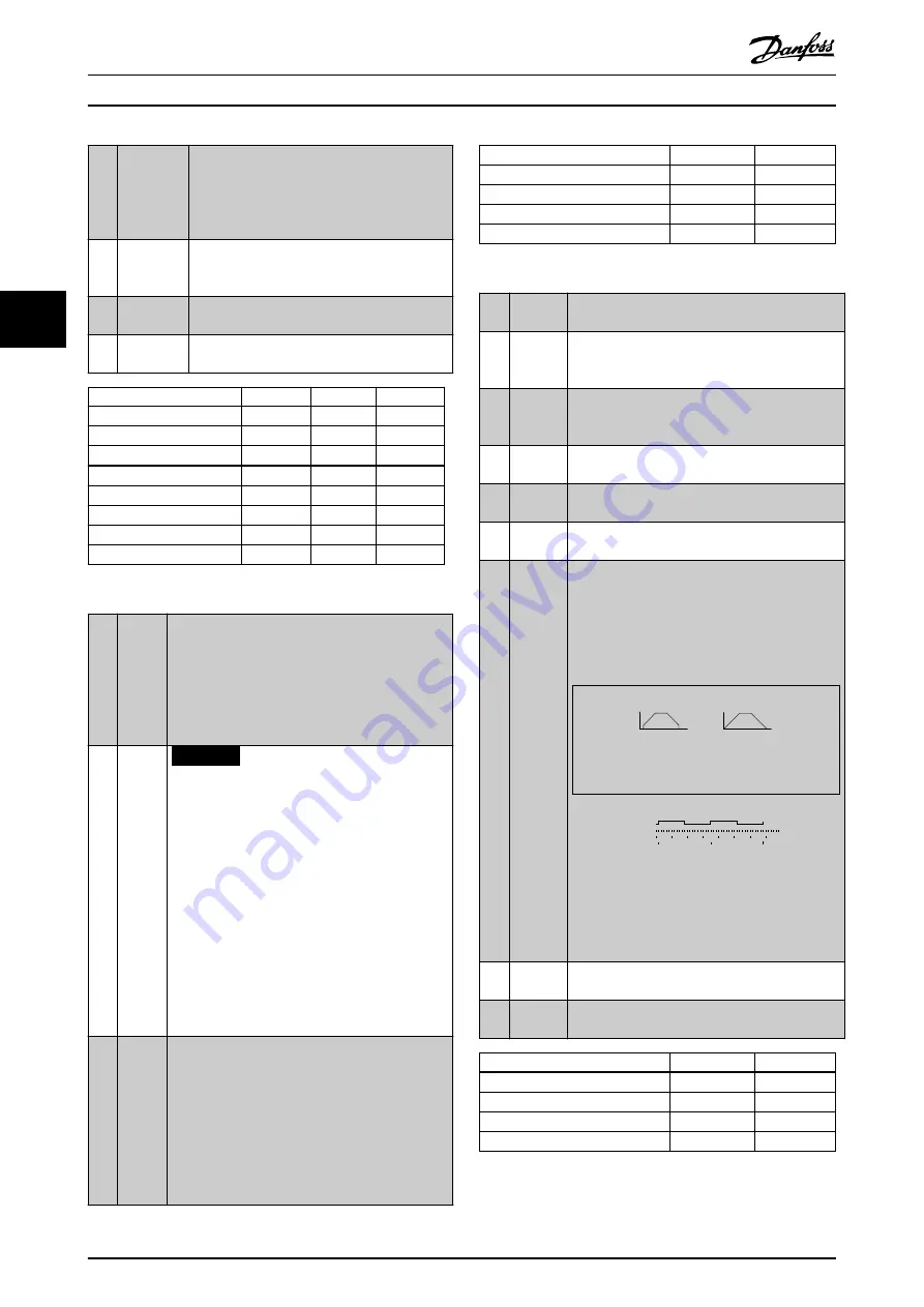
[32] Pulse
time-
based
Measures the duration between pulse flanks. This
parameter has a higher resolution at lower
frequencies, but is not as precise at higher
frequencies. This principle has a cut-off frequency,
which makes it unsuited for encoders with low
resolutions (for example 30 PPR) at low speeds.
Speed [rpm]
Speed [rpm]
Time[sec]
Time[sec]
a
b
130BB462.10
a: Low encoder
resolution
b: Standard encoder
resolution
Read Timer:
20 timer tides
Read Timer:
20 timer tides
Time Start
Time counter
Sample time
Timer
Pulse
130BB464.10
Illustration 4.11 Duration Between Pulse
Flanks
[34] Ramp
bit 0
Enables a selection from the 4 ramps available,
according to
.
[35] Ramp
bit 1
Same as ramp bit 0.
Preset ramp bit
1
0
Ramp 1
0
0
Ramp 2
0
1
Ramp 3
1
0
Ramp 4
1
1
Table 4.5 Preset Ramp Bits
Parameter Descriptions
VLT
®
AutomationDrive FC 360
50
Danfoss A/S © 7/2015 All rights reserved.
MG06C602
4
4


