52
•
Camera Operation
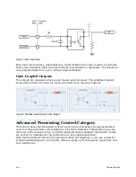
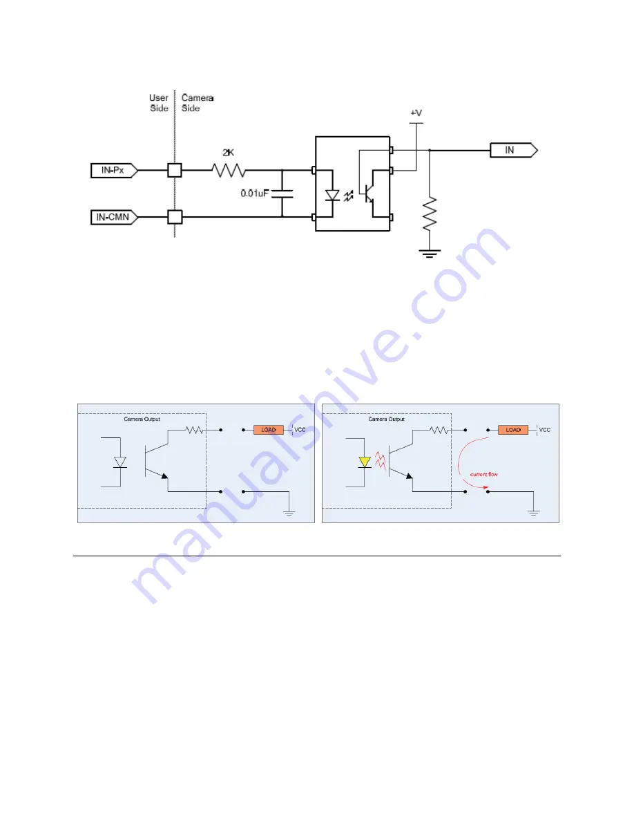
Figure 17 Opto-Coupled Input
Each input incorporates a signal debounce circuit (following the opto-coupler) to eliminate
short noise transitions that could incorrectly be interpreted as a valid pulse. The duration is
user programmable from 1 µs to 255 µs using CamExpert.
Opto-Coupled Outputs
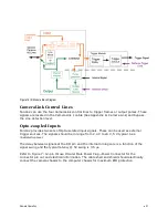
The outputs are unpowered devices and require external power. The simplified diagram
below demonstrates the need for a pull-up resistor when using the outputs.
Figure 18: Simplified General Purpose Output Diagram
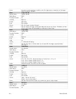
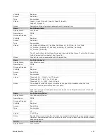
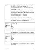
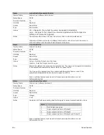
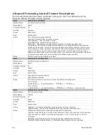
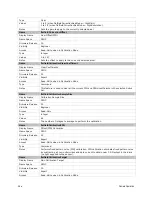
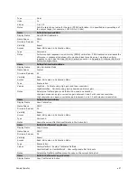
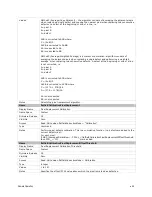
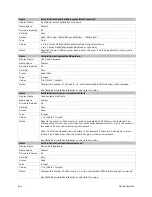
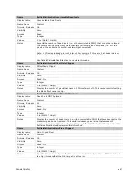
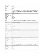
Advanced Processing Control Category
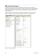
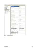
The Falcon2 Advanced Processing controls, as shown by CamExpert, groups parameters
used to configure Defective Pixel Detection, Flat Field calibration. Parameters in gray are
read only, either always or due to another parameter being disabled. Parameters in black
are user set in CamExpert or programmable via an imaging application.
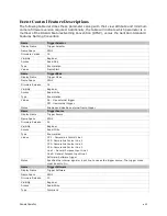
Note that the features listed in the description table but tagged as
Invisible
are usually for
Teledyne DALSA Support or third party software usage—and not typically required by end-
user applications.
Содержание FA-80-12M1H-XX-R
Страница 1: ...Falcon2 Camera User s Manual 4M 8M and 12M Area Imaging P N 03 032 20107 04 www teledynedalsa com ...
Страница 14: ...14 The Falcon2 Cameras Figure 3 Quantum Efficiency INSERT QE GRAPH HERE ...
Страница 17: ...The Falcon2 Cameras 17 Mechanicals Figure 5 Camera Mechanical ADD MECHANICAL PDF HERE ...
Страница 53: ...Camera Operation 53 Figure 19 Advanced Processing Control ...


