Software and Hardware Setup
•
21
•
Keep leads as short as possible in order to reduce voltage drop.
•
Use high-quality linear supplies in order to minimize noise.
Note: If your power supply does not meet these requirements, then the camera
performance specifications are not guaranteed.
Camera Link Data Connector
The cameras use two mini-Camera Link SDR-26 cables transmitting the Camera Link Full or
Extended configuration. For a description of the connectors and the Full and Extended
configurations refer here,
Data Connector: Camera Link
.
Output Signals, Camera Link Clocking Signals
These signals indicate when data is valid, allowing you to clock the data from the camera to
your acquisition system. These signals are part of the Camera Link configuration and you
should refer to the Camera Link Implementation Road Map, available at our
Knowledge
Center
, for the standard location of these signals.
Input Signals, Camera Link
The camera accepts control inputs through the mini-Camera Link SDR-26F connector.
The camera ships (factory setting) in internal sync, and internally triggered integration.
Frame Start Trigger (EXSYNC)
The EXSYNC signal tells the camera when to integrate and readout the image. It can be
either an internally generated signal by the camera, or it can be supplied externally via CC,
GPIO, and software command.
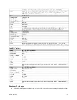
LEDs
The camera is equipped with an LED on the back to display the operational status of the
camera. The table below summarizes the operating states of the camera and the
corresponding LED states. When more than one condition is active, the LED indicates the
condition with the highest priority.
Color of Status LED
Meaning
Off
No power or hardware malfunction
Red solid
Warning (e.g. temperature)
Red solid
Fatal error state
Blue solid
Upgrading internal firmware
Blue slow blinking
Camera waiting for warm up to complete
Blue solid
At initial power up and when acquisition is disabled. This happens when changing a
camera feature that effects the image output (e.g. aoi, bit depth, etc.)
Green solid
Free-running acquisition
Содержание FA-80-12M1H-XX-R
Страница 1: ...Falcon2 Camera User s Manual 4M 8M and 12M Area Imaging P N 03 032 20107 04 www teledynedalsa com ...
Страница 14: ...14 The Falcon2 Cameras Figure 3 Quantum Efficiency INSERT QE GRAPH HERE ...
Страница 17: ...The Falcon2 Cameras 17 Mechanicals Figure 5 Camera Mechanical ADD MECHANICAL PDF HERE ...
Страница 53: ...Camera Operation 53 Figure 19 Advanced Processing Control ...

