Camera Operation
•
45
Visibility
Beginner
Access
Read-Only
Type
Enumeration
Values
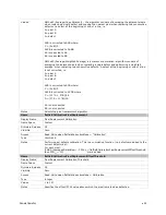
Input 1, Input 2, Input 3, Input 4, Input 5, Input 6
Output 1, Output 2
Notes
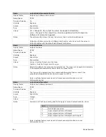
Description of the physical pin associate with the logical line.
Name
linePinAssociation
Display Name
Line Pinout
Name Space
DFNC
Firmware Release
00
Visibility
Beginner
Access
Read-Only
Type
Enumeration
Values
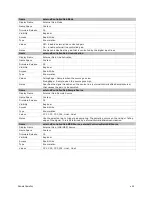
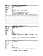
H1_Pin6Pos_Pin5Neg, H1_Pin11Pos_Pin12Neg, H1_Pin3_Pin4, H1_Pin7_Pin8
C1_Pin22Pos_Pin9Neg, C1_Pin10Pos_Pin23Neg, C1_Pin24Pos_Pin11Neg,
C1_Pin12Pos_Pin25Neg
The H1 prefix refers to the Hirose Power and input cable (See Figure 7) while the C1 refers
to the Cameralink 1 connector( See Figure 36 )
Notes
Physical pin location associated with the logical line.
Name
lineDetectionLevel
Display Name
Line Detection Level
Name Space
DFNC
Firmware Release
00
Visibility
Beginner
Access
Read-Write
Type
Enumeration
Values
Threshold_2_4 - [2.4V] – for TTL inputs
Threshold_6_0- [ 6V] – for 12 V input
Threshold_12_0 – [12V] – for 24 V input
Notes
The voltage at which the signal is treated as a logical high. Available when the Line
selector is set to a general purpose input (GPI).
Note: This value is for both general purpose inputs (i.e. setting this value sets it for both
Line 1 and Line 2).
Name
lineDebouncingPeriod
Display Name
Line Debouncing Period
Name Space
DFNC
Firmware Release
00
Visibility
Beginner
Access
Read-Write
Type
Enumeration
µs
Values
1 to 255 µs
Notes
Specifies the minimum length of an input line voltage transition before recognizing a signal
transition. Available when the Line selector is set to an input. Each input line stores its own
debouncing period.
Name
LineInverter
Display Name
Line Inverter
Содержание FA-80-12M1H-XX-R
Страница 1: ...Falcon2 Camera User s Manual 4M 8M and 12M Area Imaging P N 03 032 20107 04 www teledynedalsa com ...
Страница 14: ...14 The Falcon2 Cameras Figure 3 Quantum Efficiency INSERT QE GRAPH HERE ...
Страница 17: ...The Falcon2 Cameras 17 Mechanicals Figure 5 Camera Mechanical ADD MECHANICAL PDF HERE ...
Страница 53: ...Camera Operation 53 Figure 19 Advanced Processing Control ...

