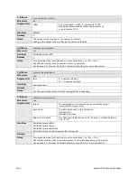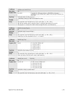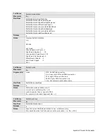
104
•
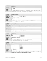
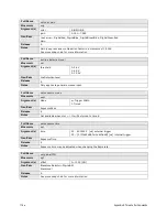
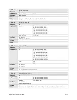
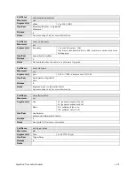
Appendix D: Internal Flat Field Calibration Algorithms
o
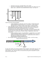
Subtract the previously calibrated offset values (FPN).
o
Calculate the multiplication factor necessary to achieve the target value. The
target value is calculated using
flatfieldCalibrationTarget.
See Figure 37.
Figure 37. Monochrome Flat Field Gain Calibration
o
If the calculated gain is less than 1 then the number of clipped gain pixels
(
flatfieldCalibrationGainPixelsClipped)
is incremented. A large number of
clipped pixels may indicate a poorly chosen target or exposure setting.
•
If the calculated pixel gain is greater than the pixel replacement threshold (see
flatfieldCalibrationPixelReplacementGainThreshold
) then the pixel is marked for
replacement and the number of dead pixels replace is incremented
(
flatfieldCalibrationDeadPixelsReplaced
). These pixels will have the maximum gain
correction but will not reach the target. By default the replacement threshold is set
to the highest correctable value so that the number of dead pixels that are not
replaced is 0.
o
If the calculated pixel gain is not correctable (i.e. greater than 1.5 or 2 when
flatfieldCalibrationGainMode
is
HighResolution
or
HighGain
) but less than the
replacement threshold then the gain is set to maximum and the number
of
dead pixels not replaced is incremented
(
flatfieldCalibrationDeadPixelsNotReplaced)
•
Once the gain values are calculated, the values are used to correct the image.
For the color cameras, the process is similar with the exception of the target value. For color
cameras each color has its own target based on the average of each color multiplied by a
factor (approx. 1.25). After each color is corrected the color gains are adjusted to set the
pixels to the maximum color.
Target
ADC
Pixel
xy
PRNU
xy
Multiplier
Clipped Gain
Correctable
1
“Dead” Pixels
NOT Replaced
0
1.5
or
2.0
(See
flatfieldCalibrationGainMode
)
(
flatfieldCalibration
PixelReplacement
GainThreshold
)
“Dead” Pixels Replaced
Calibrated Flat Field Gain Values
Gain(PRNU)
Содержание FA-80-12M1H-XX-R
Страница 1: ...Falcon2 Camera User s Manual 4M 8M and 12M Area Imaging P N 03 032 20107 04 www teledynedalsa com ...
Страница 14: ...14 The Falcon2 Cameras Figure 3 Quantum Efficiency INSERT QE GRAPH HERE ...
Страница 17: ...The Falcon2 Cameras 17 Mechanicals Figure 5 Camera Mechanical ADD MECHANICAL PDF HERE ...
Страница 53: ...Camera Operation 53 Figure 19 Advanced Processing Control ...

