


Cryo-con Model 24C
Appendix H: Rear Panel Connections
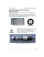
Control Loop #1 Connections
Rear panel Primary Heater Output (Loop #1) connections are made using a three-pin
banana-plug on the rear panel.
Pin
Function
Hi
Heater Output High
Lo
Heater Output Low
EGND
Earth-Ground
Table 40: Loop 1 Connections
Caution:
The Model 24C has an automatic control-on-power-up
feature. If enabled, the controller will automatically begin controlling
temperature whenever AC power is applied. For a complete
description of this function, please see the Auto-Ctl function in the
System Functions menu
section.
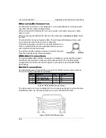
Control Loop #2 and Relay Connections
Connection to the Loop #2 Output is made on the rear panel using the 10-pin
detachable terminal block provided.
Pin
Function
1
Loop #2 Heater Output High
2
Loop #2 Heater Output Low
3
Relay #1 N.O.
4
Relay #1 Common.
5
Relay #2 N.O.
6
Relay #2 Common.
7
Loop #3 output High
8
Loop #3 output Low
9
Loop #4 output High
10
Loop #4 output Low
Table 41: Loop #2 and Digital Output Connections
183


