


Cryo-con Model 24C
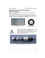
Appendix H: Rear Panel Connections
Caution
: Any disconnected inputs to the Model 24C should
be configured to a sensor type of 'None'. This will turn the
input off and prevent the high-impedance pre-amplifiers from
drifting.
i
Note:
The input connectors on the Model 24C will mate with
either DIN-5 or DIN-6 plugs. Wiring is identical. If a DIN-6 plug is
used, Pin 6 is not connected. Do not connect to pin 3 of either
connector.
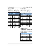
Recommended color codes for a sensor cable are as follows:
Color Code
Signal
Pin
White
Exci)
5
Green
Excitation(-)
1
Red
Sense(+)
4
Black
Sense(-)
2
Table 39: Sensor Cable Color Codes
The cable used is Belden 8723. This is a dual twisted pair cable with individual
shields and a drain wire. The shields and drain wire are connected to the connector's
metal backshell in order to complete the shielding connection.
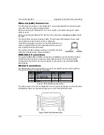
A four-wire connection is recommended in order to eliminate errors due to lead
resistance. Cryogenic applications often use fine wires made from specialty metals
that have low heat conduction. This results in high electrical resistance and, therefore,
large measurement errors if the four-wire scheme is not used.
Four-wire connection to diode and resistive type sensors is diagrammed below:
Figure 8: Diode and Resistor Sensor Connections
182


