


Cryo-con Model 24C
Remote Programming Guide
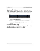
The Standard Event Register
The Standard Event Register (ESR) is defined by the SCPI to identify various
standard events and error conditions. It is queried using the Common Command
*ESR? This register is frequently used to generate an interrupt packet, or service
request when various I/O errors occur.
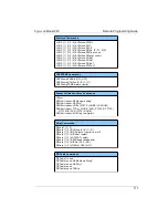
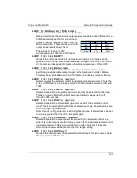
Bits in the ESR are defined as follows:
ESR
Bit7
Bit6
Bit5
Bit4
Bit3
Bit2
Bit1
Bit0
OPC
QE
DE
EE
CE
PWR
Where:
Bit7 – OPC:
Indicates Operation Complete.
Bit5 – QE:
Indicates a Query Error. This bit is set when a syntax error has
occurred on a remote query. It is often used for debugging.
Bit4 – DE:
Indicates a Device Error.
Bit3 – EE:
Indicates an Execution Error. This bit is set when a valid command
was received, but could not be executed. An example is attempting to edit a
factory supplied calibration table.
Bit2 – CE:
Indicates a Command Error. This bit is set when a syntax error
was detected in a remote command.
Bit0 – PWR:
Indicates power is on.
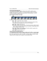
The Standard Event Enable Register
The Standard Event Enable Register (ESE) is defined by the SCPI as a mask register
for the ESR defined above. It is set and queried using the Common Command *ESE.
Bits in this register map to the bits of the ESR. The logical AND of the ESR and ESE
registers sets the Standard Event register in the Status Byte (STB).
113


