


Cryo-con Model 24C
Basic Setup and Operation
Using Thermocouple Sensors
Thermocouple temperature sensors offer an extremely wide range of operation. They
can also be inexpensive and easy to install. However, devices used in cryogenic
applications are often difficult to apply because they exhibit poor sensitivity at low
temperature and are generally constructed with metals that are difficult to use. In
order to obtain the best possible measurement accuracy, the recommendations given
here should be carefully applied.
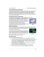
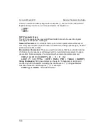
Installing the Thermocouple Module
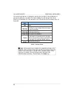
All thermocouple sensors require the use of an optional Cryo-con external
thermocouple module (4039-004). This module plugs into any
sensor input channel of a Model 24C. Up to four modules can
be installed on a single instrument and they can easily be
added or removed at any time. They are powered by the Model
24C and perform amplification, cold-junction compensation,
open sensor detection and connection to copper.
Internal switches are used to select the cold junction
compensation for specific types. Open the module and use the
switches to select types K, E, T, AuFe 0.7% or off.
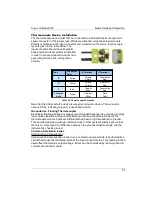
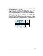
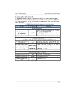
Module Configuration
Before a thermocouple module can be used, the thermocouple type must be set into
the module's internal switches. This selects the cold-junction compensation method.
To access the switches, remove the cover by removing the
two screws from the plastic cover.
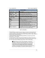
The type is set by the four switches shown here. Settings are
E, K or T, AuFe 0.7% and OFF. The Off setting disables cold-
junction compensation. Select the type by sliding the proper
switch to the right. Ensure that there is only one type selected.
Next, replace the plastic cover on the module. The
thermocouple module is now ready for use.
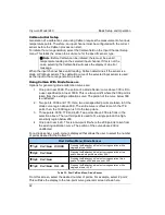
Instrument Setup
Instrument setup is performed as follows:
1. Connect the thermocouple module to any of the available input channels.
2. From the front panel, go to the Input Channel Configuration menu by pressing
the appropriate
ChA
or
ChB
key. Next, scroll down to the Sen: field and
select the sensor by pressing the
Next
key. When the proper thermocouple
type is displayed, press the
Enter
key.
3. Scroll down to the Input Config field and press the Enter key to display the
Thermocouple Sensor Configuration Menu.
4. Optionally perform the offset calibration procedure described below.
5. Return to the Home screen by pressing the
Home
key several times.
95
Figure 6: Thermocouple
Switches
Figure 5: Thermocouple
Module


