154
Cisco Aironet 1520, 1130, 1240 Series Wireless Mesh Access Points, Design and Deployment Guide, Release 6.0
OL-20213-01
Adding and Managing Mesh Access Points with Cisco WCS
Adding Mesh Access Points to Maps with Cisco WCS
After you add the .PNG, .JPG, .JPEG, or .GIF format floor plan and outdoor area maps to the Cisco WCS
database, you can position mesh access point icons on the maps to show where they are installed in the
buildings.
To add mesh access points to floor plan and outdoor area maps, follow these steps.
Step 1
Click the desired floor plan or outdoor area map in the Coverage Areas component of the General tab.
Cisco WCS displays the associated coverage area map.
Step 2
From the Select a command drop-down menu, choose
Add Access Points
and click
GO
.
Step 3
On the Add Access Points window, choose the mesh access points to add to the map.
Step 4
Click
OK
to add the mesh access points to the map and display the Position Access Points map.
Note
The mesh access point icons appear in the upper left area of the map.
Step 5
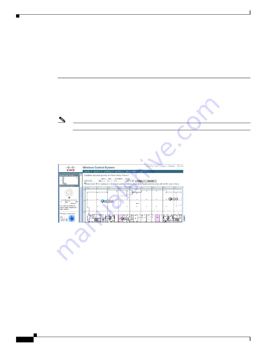
Click and drag the icons to indicate their physical locations.
Step 6
Click each icon and choose the antenna orientation in the sidebar (See
).
Figure 88
Antenna Sidebar
The antenna angle is relative to the map’s X axis. Because the origin of the X (horizontal) and Y
(vertical) axes is in the upper left corner of the map, 0 degrees points side A of the mesh access point to
the right, 90 degrees points side A down, 180 degrees points side A to the left, and so on. The antenna
elevation is used to move the antenna vertically, up or down, to a maximum of 90 degrees.
Make sure each mesh access point is in the correct location on the map and has the correct antenna
orientation. Accurate mesh access point positioning is critical when you use the maps to find coverage
holes and rogue access points.
Refer to this location for further information about the antenna elevation and azimuth patterns:
http://www.cisco.com/en/US/products/hw/wireless/ps469/tsd_products_support_series_home.html


