


20
3. Installation
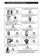
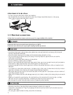
• Be sure to insert the cable cores
into the proper position of the
terminal block completely.
• Faulty wiring may cause not only
abnormal operation but also
damage to pc board.
• Fasten each screw sufficiently.
• To check the complete insertion,
pull the cable slightly.
CAUTION
Peeling of the connecting cable's covering must be 10 mm.
If shorter, a defective contacting may occur.
If longer, a short circuit may occur.
Terminal block
Cable clamp
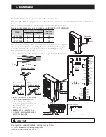
Connection diagrams
Unit side terminal
Power supply
Earth
N
L
(N)
(L)
1
2
3
Earth wire
Power supply cord
(N)
(L)
3
2
1
L
POWER
N
ON
Reset
SW.
Pump
SW.
OFF
PCB
(TERMINAL)
3
4
2
1
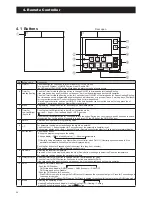
Remote
Controller
1
2
3
4
5
6
7
17
18
19
20
21
22
23
Humidity
Sensor
COM
DHW Remote
Contact
ON/OFF
or
EHS Alarm
GND
24VAC
COM
Control
DHW
T.probe
OUTDOOR
T.probe
BUFFER
T.probe
Mix water
T.probe
3-way
mixing
valve
RS485
+
-
Dehumidifier
Alarm
Pump1
Pump2
Neutral
N.C.
Neutral
EHS
Heating
Cooling
mode
output
Phase
Signal
3-way
valve
8
9
10
11
12
13
14
Dual Set
Point
Control
Heating
Cooling
mode
Flow
switch
Night
mode
Low
tariff
RS485
GND
45
46
47
48
49
50
31
32
24
25
26
27
28
29
30
15
16
N
41
42
43
44
51
52
Electric
heater
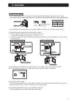
10 mm
30 mm
Crimp-on terminal
Stripped wire :10mm
Sleeve
Terminal block
Crimp-on terminal
Sleeve
PCB(Terminal)
Circuit
breaker
Distribution
board
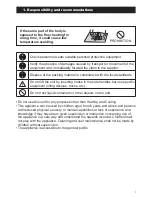
Be sure to use an exclusive power source with a circuit breaker.
Respecting the following designation, use cables whose wires size are more than the designated one in the table
below.
Power cord and circuit breaker shall be approved according to EN standard.
Supply cord must be approved in compliance with IEC60245 IEC57 (H05RN-F).
Peel ends of connecting cables in accordance with dimension in the diagram.
Use crimp-on terminals with insulating sleeves as illustrated in the diagram
below for connecting the wires to the terminal block or PCB(Terminal).
Stranded conductors shall not be soldered.
• Use a circuit breaker with a 3 mm clearance of air gap between the contacts.
Model
Power supply cord(mm
2
)
Breaker
capacity
MAX.
MIN.
AEYC-0639U
2.0
1.5
16
AEYC-1039U
4.0
3.5
20
AEYC-1639U
5.5
4.0
32
Содержание AEYC-0639U-CH
Страница 156: ...20810030 M ...