


151
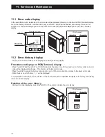
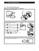
11. Service and Maintenance
AEYC-0639U-CH
AEYC-1039U-CH
Warning when you fix electric components !
Electric Shock !
Don't touch electrically charged parts, as electric shock
may occur even if they are switched off.
WARNING !
Do not touch any part of the electric circuit
(including the wiring of thermistor and others),
as it has high voltage against the ground.
Pay attention not to damage the insulated wire
when you tighten the screw, as the exposed wire
may cause electric shock or malfunction.
Do not ground the oscilloscope when you operate.
You might destroy it. Also do not touch any metal
part of the oscilloscope while operating.
How to release
locking terminals( )
Lever
To release the
terminals ( ),
press the locking
lever and pull.
:Not available for the model without FUSE CF7
Caution
Electric Shock
High Voltage
Be sure to wait at least 5 min. after turning off the power
and to confirm the voltage between the connector pins
of pump connector 17 [between white and black ]
is less than DC10V with a tester before servicing.
BL
GR
OR
Y
COLOR OF WIRE
: BLACK
: WHITE
: RED
: GREEN
: BROWN
B
W
R
G
BR
: BLUE
: GRAY
: ORANGE
: YELLOW
GR
GR
COMPRESSOR
U
(
R
)
V
(
S
)
W
(
T
)
R
BL
R
B
W
W
B
B
B
B
W
B
W(T)
V(S)
U(R)
9
8
7
OR
Y
REACTOR
FUSE CF2
250V
T3.15A
FUSE CF7
250V
T3.15A
18
MOTOR
(FAN) PUMP
17
EXP.V.
23
34 33
28
32
31
10 11
PCB
(MAIN)
SENSOR(TEMP., SUCTION)
SENSOR(TEMP., DEFROST)
SENSOR(TEMP., DISCHARGE)
SENSOR(TEMP., OUTDOOR)
SENSOR(TEMP., OUTGOING)
4 WAY V.
DEFROST HEATER
SENSOR(TEMP., RETURN)
B
W
3
4
2
1
6
8
6
4
ON
OFF
TERMINAL BLOCK
GR
BL
W
R
W
B
B
B
G/Y
BL Y
B
R
G/Y
W
N
L
POWER
1
2
3
PCB
(CONTROLLER)
PCB
(TERMINAL)
7
3
4
5
TRANSFORMER
2
1
Remote
Controller
1
2
3
4
5
6
7
17
18
19
20
21
22
23
Humidity
Sensor
COM
DHW Remote
Contact
ON/OFF
or
EHS Alarm
GND
24VAC
COM
Control
DHW
T.probe
OUTDOOR
T.probe
BUFFER
T.probe
Mix water
T.probe
3-way
mixing
valve
RS485
+
-
Dehumidifier
Alarm
Pump1
Pump2
Neutral
N.C.
Neutral
EHS
Phase
Signal
3-way
valve
8
9
10
11
12
13
14
Dual Set
Point
Control
Heating
Cooling
mode
Flow
switch
Night
mode
Low
tariff
RS485
GND
45
46
47
48
49
50
31
32
24
25
26
27
28
29
30
15
16
N
41
42
43
44
51
52
Electric
heater
RESET SW.
PUMP SW.
RAM CLEAR
EEPROM
DIP SW.
FUSE CF1
(250V T10A)
Heating
Cooling
mode
output
Wiring Diagram
Содержание AEYC-0639U-CH
Страница 156: ...20810030 M ...