


Chapter 6 Key Functional Parameter Explanation In Detail 200 Series General Purpose Vector AC Drive
64
counting input" (function 18). When the pulse frequency is high, the S5 port must be used.
F4-30 Set
count
value
Set range: 1
~
32000
Factory default: 1000
F4-31 Designated count value
Set range: 1
~
32000
Factory default: 1000
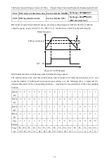
The count value needs to be collected by the multi-function digital input terminal. In the application, the
corresponding input terminal function needs to be set to "terminal count input" (function 26). When the
pulse frequency is high, the S5 port must be used.
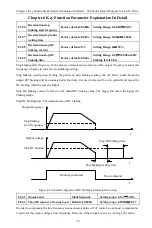
When the count value reaches the set count value F4-30, "set count value reached" ON signal is output by
the multifunctional digital , and then the counter stops counting.
When the count value reaches the designated count value F4-31, the multifunctional digital output
"designated count value reached" ON signal, at this time the counter continues to count, and the counter
stops until the "set count value" reached.
The designated count value F4-31 should not be bigger than the set count value F4-30. Figure 6-8 is a
schematic diagram of the set count value arrival and designated count value arrival function.
Figure 6-8 Schematic diagram of setting count value specified and designated count value specified
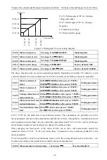
F5-13
Frequency arrival
(FAR) detection width
Factory default: 5.0%
Setting range: 0.0
~
100.0% ( Maximum
output frequency)
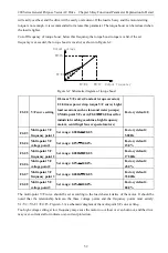
The output frequency of AC Drive output pulse signal in the positive and negative detection width of
setting frequency, the detail is as the following figure 6-9.
SP1
、
T1
、
T0
t
t
Set frequency
Output frequency
Detection amplitude=F5-13*F0-05/100.0%
Figure 6-9 Frequency arrival diagram
Count pulses
input
1 2
1 2 3
1112
10
20 21
19
Count reset input
FF-32=0
F4-31=11
FF-32=11
Designated count value
reached output
F4-30=20
FF-32=20
Designated count value
reached output
FF-32:
Count value