Chapter 3 Mechanical and Electrical Installation 200 Series General Purpose Vector AC Drive
26
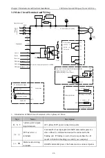
3.2 Main Circuit Terminal and Wiring
R
S
T
+24V
S2
S6
S5
S3
COM
10V
GND
V1
V2
DC 0
~
10V
Input power supply
M
Motor
SP1
COM
FM1
U
V
W
10V auxiliary power supply
PB
(+)
(-)
P
Braking resistor
DC reactor
Braking unit
Motor
casing
MCCB
JP2 Jumper selection
JP9 Jumper selectionmA/V
S5 can receive high-speed pulse of 0~100KHZ
5V
GND
Relay
1k
~
5k
Shield able
24V
Analog signal output:
Relay output:
Analog input
0
~
20mA/0
~
10V
0
~
20mA/0
~
10V
Output voltage range
:
0V
~
24V
Output current range
:
0mA
~
50mA
Open-circuit collector output/ High-speed pulse output:
AC Driver and motor earthing
Digital input
Th
re
e p
ha
se
380
v
50/
60H
z
AC250V
,
3A
,
DC30V
,
1A
COS
φ
=0.4
S1
S4
Forward
Reverse
Fault reset
Multi-segment input 2
Multi-segment input 1
Multi-segment input 3
TA1
TC1
TA0
TB0
TC0
FM2
JP19 Jumper selection mA/V
0
~
20mA/0
~
10V
COM
485+
485-
E
TB1
1
、
Introduction of Main Circuit Terminals of the 3-phase AC Drive:
Sign
Name
Description
R
、
S
、
T
3-phase power supply
input terminals
AC 3-phase 380V power connections points
(+)
、
(-)
DC bus wire(+,-)
terminals
Common DC bus input point (G30KW and smaller power ac
drive without (-) terminal and cannot be connected to the
braking unit. If braking is used, it needs to purchase the -B
model with built-in braking provided by our company)
(+)
、
PB
Brake resistor wiring
terminals
G30kW and smaller power, the brake resistor connected points


