background image

200 Series General Purpose Vector AC Drive              Chapter 5 Functional Parameter Simple List 

45 

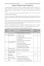
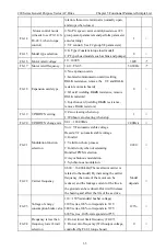
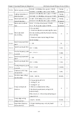
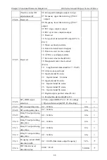
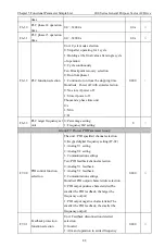
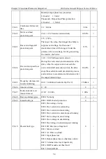
F5-15  FDT lag detection value 000.0%

100.0%(FDT Electric Level) 

5.0% 

*


F5-16  FDT torque level value  0.0%

250.0% 

100.0%


F5-17 

FDT torque level 
detection lagged value 

0.0%

100.0%(FDT Electric Level) 

5.0% 


F5-18 FM1output 

selection  00: Operating frequency: 0

Maximum output 

frequency 
01: Setting frequency: 0

Maximum output 

frequency 
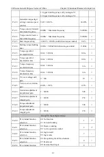
02: Bus voltage: 0

2 times standard bus 

03: Output current: 0

2 times ac drive rated 

current  
04: Output voltage: 0

1.2 times ac drive 

rated voltage 
05: Operating speed: 0

rotation speed 

corresponding to maximum frequency06:   
Output power: 0

2 times motor rated power 

07: Setting torque: 0

2 times ac drive rated 

current 
08: Output torque: 0

2 times ac drive rated 

current 
09: PID setting: 0.0

100.0% 

10: PID feedback: 0.0

100.0% 

11: Analogue V1 input value: 0.00

10.00V 

12: Analogue V2 input value: 0.00

10.00V/ 0

20mA 

13: HDI high speed pulse: 0.00

100.00kHz 

14: Specify output percentage F5-35: 0.0

100.0% 


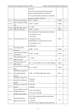
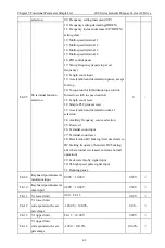
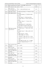
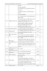
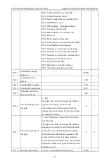
F5-19  FM2 output selection 


F5-20 

HDO high speed pulse 
output selection 


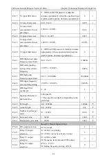
F5-21 

FM1 output lower limit 
percentage  

0.0

100.0% 

0.0% 


F5-22 

FM1 lower limit 
corresponding output 

0.00

10.00V 

0.00V 


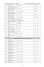
F5-23 

FM1 output upper limit 
percentage 

0.0

100.0% 

100.0%


F5-24 

FM1 upper limit 
corresponding output 

0.00

10.00V 

10.00V


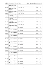
F5-25 

FM2 output lower limit 
percentage 

0.0

100.0% 

0.0% 


F5-26 

FM2 lower limit 
corresponding output 

0.00

10.00V 

0.00V 


F5-27 

FM2 output upper limit 
percentage 

0.0

100.0% 

100.0%


Содержание 200 Series

Страница 1: ...200 Series General Purpose Vector AC Drive Operation Manual Material Version V3 4 Date of Filing 2021 04 14 Company Standard Q 903703SSC002 2019 ...

Страница 2: ...urpose AC Drive Product Outline Drawing and Installation Hole Size 15 2 8 1 270 Series 11 18 5KW Outline and Outer Size of Hang Machine Plastic Casing AC Drive 15 2 8 2 270 Series 22 110KW Outline and Outer Size of Hang Machine Metal Casing AC Drive 15 2 8 3 270 Series 132 400KW Outline and Outer Size of Hang Machine Metal Casing AC Drive 16 2 9 280 Series Factory Explosion proof AC Drive Movement...

Страница 3: ...n Detail 58 Chapter 7 Communication Protocol 68 7 1 Communication Allocation 68 7 2 Salve Machine Address 68 7 3 Function Code 03 Present Reading the Variant the Function Code 68 7 4 Function Code 06 Stands for the Function Code of Writing Variable 70 Chapter 8 Troubleshooting 72 8 1 Faults and Actions 72 8 2 Common Fault and Handling Methods 74 ...

Страница 4: ... damaged 10 AC drive cannot be repaired or maintained immediately because there is still high voltage on the filter capacity after the power off It needs to wait for more than 5 minutes before using a multimeter to measure the bus voltage the voltage between and should not exceed 36V 11 Do not share the ground terminal PE with the power line terminal N 1 2 Notes 1 Insulation checking of motors Mak...

Страница 5: ...tion The incineration of plastic will produce poisonous gas please deal with it as industrial waste 6 Pay attention when the cable length is too long When the motor cable length is longer than 50m it is recommended to install an output reactor or output filter If the motor cable length exceeds 100m An output reactor or output filter must be installed otherwise the motor insulation is easily damage...

Страница 6: ... Power KW Fan pump type General purpose P G Type Input voltage level Mark Mark Mark Brake unit F Mark Null Null With brake unit B Z ET Note 1 For G22KW and G30KW type ac drive if braking is needed it needs to purchase our the B model with built in braking 2 For G37KW and bigger power ac drive if braking is needed it needs to purchase our external braking unit 2 2 Nameplate 2 3 Model and Technical ...

Страница 7: ... P160T4 N 192 0 256 0 253 300 132 160 200 G160 P185T4 N 231 0 307 0 300 340 160 185 200 G185 P200T4 N 242 0 350 0 340 380 185 200 200 G200 P220T4 N 250 0 385 0 380 420 200 220 200 G220 P250T4 N 280 0 430 0 420 470 220 250 200 G250 P280T4 N 355 0 468 0 470 520 250 280 200 G280 P315T4 N 396 0 525 0 520 600 280 315 200 G315 P350T4 N 445 0 590 0 600 640 315 350 200 G350 P400T4 2N 500 0 665 0 640 690 3...

Страница 8: ... 0 665 0 640 350 230 QM400T4 F ET A 565 0 785 0 690 400 230 QM450T4 F ET A 650 0 825 0 800 450 230 QM500T4 F ET A 700 0 883 0 860 500 230 QM550T4 F ET A 770 0 975 0 950 550 230 QM630T4 F ET A 1000 0 1400 0 1100 630 260 Model and technical parameters VFD Model Input V Power Capacity KVA Input Current A Output Current A Adaptive Motor KW 260 KH30T4B A 3 phase 380V 15 40 0 62 0 60 30 260 KH37T4B A 57...

Страница 9: ...ptive Motor KW 270 PS11T4B 3 phase 380V 15 17 0 26 0 25 0 11 270 PS15T4B 21 0 35 0 32 0 15 270 PS18 5T4B 24 0 38 5 37 0 18 5 270 PS22T4B 30 0 46 5 45 0 22 270 PS30T4 40 0 62 0 60 0 30 270 PS37T4 57 0 76 0 75 0 37 270 PS45T4 69 0 92 0 90 0 45 270 PS55T4 85 0 113 0 110 0 55 270 PS75T4 114 0 157 0 150 0 75 270 PS93T4 134 0 180 0 176 0 93 270 PS110T4 160 0 214 0 210 0 110 270 PS132T4 192 0 256 0 253 0...

Страница 10: ...80 FB18 5T4B X 24 0 38 5 37 18 5 280 FB22T4B X 30 0 46 5 45 22 280 FB30T4B X 40 0 62 0 60 30 280 FB37T4 X 57 0 76 0 75 37 280 FB45T4 X 69 0 92 0 90 45 280 FB55T4 X 85 0 113 0 110 55 280 FB75T4 X 114 0 157 0 150 75 280 FB93T4 X 134 0 180 0 176 93 280 FB110T4 X 160 0 214 0 210 110 280 FB132T4 X 192 0 256 0 253 132 280 FB160T4 X 231 0 307 0 300 160 280 FB185T4 X 242 0 350 0 340 185 280 FB200T4 X 250 ...

Страница 11: ... VF control 1 100 Speed control precision Open loop vector control 0 2 VF control 0 5 Torque control precision 5 time 20ms Protection function 25 types protection function Including over voltage over current overheat overload under voltage short circuit ground fault input and output default phase protect the frequency AC Drive running reliably all round Installation environment requirement Ambient...

Страница 12: ... of Hang Machine Plastic Casing AC Drive VFD Model H W D H1 W1 Installation aperture Weight Kg 200 G0 4T4B N 170 100 140 160 90 Φ5 1 8 200 G0 75T4B N 200 G1 5T4B N 200 G2 2T4B N 200 G3 0 P3 7T4B N 187 125 166 177 115 Φ5 2 5 200 G3 7 P5 5T4B N 200 G5 5 P7 5T4B 2N 248 160 184 239 150 Φ5 4 200 G7 5 P11T4B 2N 200 G11 P15T4B N 320 208 190 307 193 Φ6 7 2 200 G15 P18 5T4B N 200 G18 5 P22T4B N ...

Страница 13: ...15 200 G45 P55T4 N 200 G55 P75T4 N 605 300 290 582 200 Φ8 48 200 G75 P93T4 N 200 G93 P110T4 N 200 G110 P132T4 N 650 340 330 630 200 Φ10 52 200 G132 P160T4 N 200 G160 P185T4 N 830 500 376 806 180 180 Φ12 107 200 G185 P200T4 N 200 G200 P220T4 N 200 G220 P250T4 N 890 500 376 866 180 180 Φ12 126 200 G250 P280T4 N 200 G280 P315T4 N 200 G315 P350T4 N 1080 683 396 1050 250 250 Φ12 177 200 G350 P400T4 N 2...

Страница 14: ...Vector AC Drive Chapter2 Specifications and Selection 11 2 6 230 Series Ball Mill Special Purpose AC Drive Product Outline Drawing and Installation Hole Size Dashboard Lower door panel Rear door panel Cover base Rings H W W1 D1 D ...

Страница 15: ... Z ET A 230 QM55T4 F ET A 230 QM75T4 F ET A 1000 510 370 450 310 Φ14 95 230 QM93T4 F ET A 230 QM110T4 F ET A 230 QM132T4 F ET A 1400 700 400 620 320 Φ14 135 230 QM160T4 F ET A 230 QM185T4 F ET A 230 QM200T4 F ET A 230 QM220T4 F ET A 230 QM250T4 F ET A 1600 905 435 825 335 Φ14 195 230 QM280T4 F ET A 230 QM315T4 F ET A 230 QM350T4 F ET A 1860 1040 450 970 375 Φ14 275 230 QM400T4 F ET A 230 QM450T4 F...

Страница 16: ... Vector AC Drive Chapter2 Specifications and Selection 13 2 7 260 Series Engineering Type Vector AC Drive Product Outline Drawing and Installation Hole Size Dashboard Lower door panel Rear door panel Cover base Rings H W W1 D1 D ...

Страница 17: ...410 240 Φ12 45 260 KH75T4 2N 260 KH93T4 2N 1000 510 370 450 310 Φ14 79 260 KH110T4 2N 260 KH132T4 2N 260 KH160T4 2N 1400 700 400 620 320 Φ14 117 260 KH185T4 2N 260 KH200T4 2N 260 KH220T4 2N 260 KH250T4 2N 260 KH280T4 2N 1600 905 435 825 335 Φ14 166 260 KH315T4 2N 260 KH350T4 2N 260 KH400T4 A 1860 1040 450 970 375 Φ14 237 260 KH450T4 A 260 KH500T4 A 280 260 KH550T4 A 260 KH630T4 2N 1940 1010 1360 5...

Страница 18: ...oduct Outline Drawing and Installation Hole Size 2 8 1 270 Series 11 18 5KW Outline and Outer Size of Hang Machine Plastic Casing AC Drive VFD Model H W D H1 W1 Installation aperture Weight Kg 270 PS11T4B 320 208 190 307 193 Φ6 7 2 270 PS15T4B 270 PS18 5T4B 2 8 2 270 Series 22 110KW Outline and Outer Size of Hang Machine Metal Casing AC Drive ...

Страница 19: ...re Weight Kg 270 PS22T4B 420 270 215 404 160 Φ7 15 270 PS30T4 270 PS37T4 270 PS45T4 605 300 290 582 200 Φ8 48 270 PS55T4 270 PS75T4 650 340 330 630 200 Φ10 52 270 PS93T4 270 PS110T4 2 8 3 270 Series 132 400KW Outline and Outer Size of Hang Machine Metal Casing AC Drive Equipped with mounting eye nut W H W 1 H 1 D H 2 W 2 D 1 ...

Страница 20: ... Ø12 M10 270 PS160T4 270 PS185T4 600 850 376 77 200 2 77 500 102 200 3 102 750 168 Φ12 M10 28 270 P200T4 270 PS220T4 270 PS250T4 270 PS280T4 270 PS315T4 900 1055 450 127 200 3 127 800 204 5 200 3 204 5 955 195 Φ14 M12 79 270 PS350T4 270 PS400T4 2 9 280 Series Factory Explosion proof AC Drive Movement Product Outline Drawing and Installation Hole Size 7 5 18 5 AC drive outline drawing and outline s...

Страница 21: ...Chapter2 Specifications and Selection 200 Series General Purpose Vector AC Drive 18 22 37KW AC drive outline drawing and outline size diagram ...

Страница 22: ...200 Series General Purpose Vector AC Drive Chapter2 Specifications and Selection 19 45 75KW AC drive outline drawing and outline size diagram ...

Страница 23: ...Chapter2 Specifications and Selection 200 Series General Purpose Vector AC Drive 20 93 110KW AC drive outline drawing and outline size diagram ...

Страница 24: ...200 Series General Purpose Vector AC Drive Chapter2 Specifications and Selection 21 132 185KW AC drive outline drawing and outline size diagram ...

Страница 25: ... 200 280KW AC drive outline drawing and outline size diagram VFD Model H W D Installation aperture Weight Kg 280 FB7 5T4B X 480 310 232 Φ9 5 22 5 280 FB11T4B X 280 FB15T4B X 280 FB18 5T4B X 280 FB22T4B X 540 350 270 Φ9 5 24 280 FB30T4B X 280 FB37T4 X 280 FB45T4 X 540 360 353 5 Φ9 5 30 ...

Страница 26: ...FB185T4 X 280 FB200T4 X 850 760 388 Φ11 5 140 280 FB220T4 X 280 FB250T4 X 280 FB280T4 X 2 10 Keyboard Outline Size 1 Keyboard Outline Size mm 85 41 23 3 2 M3 2 Keyboard Back Fixed Opening Size Without Keyboard Tray mm 3 Keyboard Tray Outline Size When it needs to pull the keyboard to other cabinet door or operation floor it needs to select configuration this group TJ500 X2 0 The keyboard tray open...

Страница 27: ...ly after aiming at the panel tray during the installation when you hear the sound ka it means the installation is finished Remove the Operation Panel Install the Operation Panel 2 12 Selection of Braking Package Model KW Recommended Braking Resistor Power KW Recommended Braking Resistor Resistance Ω Braking Unit Remark 0 4 0 75KW 0 2KW 300Ω Standard built in 1 5 2 2KW 0 5KW 220Ω 3 0 3 7KW 1 0KW 13...

Страница 28: ... 16 12 1 5 1 5 0 5 5 5 20 18 2 5 2 5 0 75 7 5 32 25 4 0 4 0 0 75 11 40 32 4 0 4 0 0 75 15 50 38 6 0 6 0 0 75 18 5 50 40 10 10 1 0 22 63 50 10 10 1 0 30 100 65 16 16 1 0 37 100 80 25 25 1 0 45 123 95 35 35 1 0 55 160 115 50 50 1 0 75 225 170 70 70 1 0 93 250 205 95 95 1 0 110 315 245 95 95 1 0 132 350 300 120 120 1 0 160 400 300 150 150 1 0 185 500 410 150 150 1 0 200 500 410 185 185 1 0 220 630 47...

Страница 29: ...gh speed pulse output AC Driver and motor earthing Digital input Three phase 380v 50 60H z AC250V 3A DC30V 1A COSφ 0 4 S1 S4 Forward Reverse Fault reset Multi segment input 2 Multi segment input 1 Multi segment input 3 TA1 TC1 TA0 TB0 TC0 FM2 JP19 Jumper selection mA V 0 20mA 0 10V COM 485 485 E TB1 1 Introduction of Main Circuit Terminals of the 3 phase AC Drive Sign Name Description R S T 3 phas...

Страница 30: ... COM External connection 24v power Provide 24 V power for outside generally used as the power of digital input and output terminals and external transducers Max output current 200mA Analog input V1 GND Analog input terminal 1 1 Input voltage range DC 0V 10V 2 Input resistance 20KΩ V2 GND Analog input terminal 2 1 Input range DC 0V 10V or 4 20mA Selected by jumper JP2 on the control board 2 Input r...

Страница 31: ...e DC 0V 24V Max output current is 50mA Relay output TA0 TB0 TA0 TC0 Normal closed open terminals Relay output TA0 TB0 normal closed TA0 TC0 normal open Contact capacity AC 250V 3A DC 30V 1A TA1 TB1 TA1 TC1 Normal closed open terminals Relay output TA1 TB1 normal closed TA1 TC1 normal open Contact capacity AC 250V 3A DC 30V 1A Communication terminal 485 485 RS485 hardware circuit Support standard M...

Страница 32: ... AC Drive Chapter 3 Mechanical and Electrical Installation 29 TC1 TB1 TA1 TC0 TB0 TA0 10V S1 S3 485 S5 S2 485 SP1 FM1 GND 24V COM V2 V1 FM2 COM S6 S4 V V2 mA 1 2 3 JP2 V FM2 mA JP19 3 2 1 V FM1 mA JP9 3 2 1 mA V JP19 JP2 JP9 mA V mA V ...

Страница 33: ...isplay Interface Through the keyboard operation panel we could modify the functional parameter to the AC Drive monitor the working condition and perform the operational control start stop of AC Drive its outline and functional zone are as follows 1 LED Digital tube keyboard Specification JP300 1 digit potentiometer 2 LCD keyboard Specification JPOLED analog potentiometer ...

Страница 34: ...A V Percentage 4 3 Basic Function Code Inspection and Modification Method Description The operation panel of 200 type AC Drive adopts two level menu structure to set the parameter Press ENTER to access the function code is the first level menu and then press ENTER to access the parameter group is the second level menu The operation procedure is as the follow Fig F0 00 ENTER access MODE exit settin...

Страница 35: ...t flash bit it indicates that the function code couldn t be modified it may be caused by the following reasons 1 The function code is non modifiable parameters such as actual monitoring parameters and run recording parameters and so on 2 The function code is in the process of running it couldn t be modified and only could be modified after stop ...

Страница 36: ...d control channel Notice 4 Indicates the parameter can be modified no matter the drive runs or stops means the parameter cannot be modified while the drive is running indicates the parameter can be read only Remarks with indicates that there are parameter explanations in Chapter 6 Function Code Name Setting Scope and Introduction Factory Defaults Modify Group F0 Basic Running Parameters Group F0 0...

Страница 37: ... depends F0 11 Deceleration time 0 0 1 3200 0s Model depends F0 12 Operation channel selection 0 Keyboard start stop REMOT off 1 Terminal start stop REMOT on 2 Communication start stop REMOT flash 0 F0 13 Terminal control running mode 0 Two wire type control 1 The forward terminal starts and stops in the forward direction and the reverse terminal starts and stops in the reverse direction 1 Two wir...

Страница 38: ...UP DOWN setting 0 Zero clearing when stop 1 Without zero clearing when stop 1 F0 20 UP DOWN change rate 0 01 100 00Hz s 2 00Hz s F0 21 Modulation function selection Unit VF automatic stable voltage Decade VC automatic stable voltage 0 Invalid 1 Valid for whole process 2 Invalid only when decelerating Hundred PWM selection 0 Asynchronous modulation 1 Synchronous modulation 0000 F0 22 Carrier freque...

Страница 39: ...ns that as the load increases the output frequency of the ac drive is reduced and the load of multiple motors is evenly realized This parameter refers to the output frequency drop value when the ac drive outputs the rated load 0 00Hz F0 30 Main frequency adjustment V1 low gain 0 0 F0 31 FA 13 1 is valid 30 0 F0 31 Main frequency adjustment V1 high gain F0 30 500 0 FA 13 1 is valid 320 0 Group F1 S...

Страница 40: ...Free stop 0000 F1 06 Stop braking start frequency 0 00Hz F0 05 0 00Hz F1 07 Deceleration stop brake waiting time 0 000s 32 000s 0 000s F1 08 Deceleration stop DC braking current 0 150 0 F1 09 Deceleration stop DC braking time 0 0s 32 000s When it is 0 0s no DC braking 0 000s F1 10 Power off restart waiting time 0 0s 32 000s 2 000s F1 11 Momentary stop power generation judgment voltage 70 0 110 0 s...

Страница 41: ...tion recovery time 0 0s 100 0s 0 5s F1 23 Momentary stop restart waiting time 0 000s 10 000s 1 000s F1 24 Momentary stop power generation deceleration time 0 1s 3200 0s 3 0 Group F2 VF Control Parameter Group F2 00 V F curve setting 0 Linear V F curve Constant torque situation 1 2 0 times power drop torque V F curve Light load occasions such as fans and water pumps 3 Multi point VF curve F2 03 F2 ...

Страница 42: ... 30 0s special for ball mill 0 0s F2 14 VF overvoltage excitation gain 0 200 During the deceleration of the ac drive this parameter can suppress the rise of bus voltage and avoid over voltage faults The larger the over excitation gain the stronger the suppression effect but it is easy to cause the output current to increase or the speed to fluctuate which needs to be weighed in the application For...

Страница 43: ...atically then auto learning when rotating 2 Parameter static auto learning Without motor running 0 F3 09 Speed loop proportional gain 1 1 100 50 F3 10 Speed loop integral time 1 0 01 10 00s 1 00s F3 11 The low frequency point to switch 0 0 F3 14 5 00Hz F3 12 Speed loop proportional gain 2 1 100 30 F3 13 Speed loop integral time 2 0 01 10 00s 1 00s F3 14 The high frequency point to switch F3 11 F0 ...

Страница 44: ...ation time 0 00s 320 00s 0 01s F3 27 Torque frequency acceleration time 0 00s 320 00s 3 0s F3 28 Torque frequency deceleration time 0 00s 320 00s 3 0s F3 29 VC over voltage stall gain 0 300 10 F3 45 Vector over excitation gain 80 0 150 125 F3 46 Excitation adjustment proportional gain 1 32000 500 F3 47 Excitation adjustment integral gain 1 32000 250 F3 48 Torque adjustment proportional gain 1 3200...

Страница 45: ...PLC process reset 23 Acceleration and deceleration time 1 selection 24 Auxiliary frequency source selection 25 Reserved 26 Terminal count input 27 Terminal count reset 28 Deceleration DC braking first decelerate to DC braking frequency then start DC braking after the terminal is released continue normal operation 29 Lack water faulty signal input 30 S5 high speed pulse signal input 31 Running paus...

Страница 46: ... 0 00kHz F4 22 HDI corresponding setting of lower limit frequency 99 99 100 00 0 00 F4 23 HDI high pulse frequency upper limit F4 21 100 00kHz 20 00kHz F4 24 HDI upper frequency corresponding setting 99 99 100 00 100 00 F4 25 HDI Input filter coefficient 0 20 3 F4 26 Input less than lower limit selection 0 Output 0 1 The output lower limit corresponding to the percentage 1 F4 27 Set length 0m 3200...

Страница 47: ...Input terminal S1 status 22 Input terminal S2 status 23 Input terminal S3 status 24 Input terminal S4 status 25 Input terminal S5 status 26 Input terminal S6 status 27 Digital output specified value F5 34 31 External fan start control FA 21 F5 04 Reserved F5 05 Reserved F5 06 SP1_HDO output selection 0 Pulse output HDO F5 29 F5 32 setting 1 Open collector output SP1 F5 00 setting 1 F5 07 SP1 closi...

Страница 48: ... 0 2 times motor rated power 07 Setting torque 0 2 times ac drive rated current 08 Output torque 0 2 times ac drive rated current 09 PID setting 0 0 100 0 10 PID feedback 0 0 100 0 11 Analogue V1 input value 0 00 10 00V 12 Analogue V2 input value 0 00 10 00V 0 20mA 13 HDI high speed pulse 0 00 100 00kHz 14 Specify output percentage F5 35 0 0 100 0 0 F5 19 FM2 output selection 3 F5 20 HDO high spee...

Страница 49: ... specified value 0 0 100 0 0 0 F5 36 Motor overload pre alarm coefficient 20 100 50 F5 37 AC drive overload pre alarm coefficient 20 100 50 F5 38 Relay T2 output closing delay 0 0 3200 0s 0 0s F5 39 Relay T2 output off delay 0 0 3200 0s 0 0s Group F6 Multi speed and PLC Program Operation F6 00 PLC phase 0 Multi speed 0 target 100 0 100 0 0 0 F6 01 PLC phase 1 Multi speed 1 target 100 0 100 0 0 0 F...

Страница 50: ... 0 0 F6 16 PLC phase 0 operation time 0 0 3200 0s 0 0s F6 17 PLC phase 1 operation time 0 0 3200 0s 0 0s F6 18 PLC phase 2 operation time 0 0 3200 0s 0 0s F6 19 PLC phase 3 operation time 0 0 3200 0s 0 0s F6 20 PLC phase 4 operation time 0 0 3200 0s 0 0s F6 21 PLC phase 5 operation time 0 0 3200 0s 0 0s F6 22 PLC phase 6 operation time 0 0 3200 0s 0 0s F6 23 PLC phase 7 operation time 0 0 3200 0s ...

Страница 51: ... 33 PLC target frequency set unit 0 Percentage setting 1 Frequency HZ setting 0 Group F7 Process PID Parameter Group F7 00 PID control function selection The unit PID specified channel selection 0 Keypad digital frequency setting F7 02 1 Analog V1 setting 2 Analog V2 setting 3 Communication settings Ten PID feedback channel selection 0 Analog V1 feedback 1 Analog V2 feedback 2 Communication settin...

Страница 52: ...overshoot 1500 F7 05 PID control deviation limit 0 0 100 0 The error between specified and feedback is less than this setting PID pause adjustment 0 0 F7 06 PID feedback disconnection detected value 0 0 100 0 Feedback disconnection detection When the feedback value is less than the feedback loss detection value F7 06 the system starts the detection timing When the timing time exceeds F7 07 the ac ...

Страница 53: ...5 PID feedback overpressure fixed output 0 0 100 0 Maximum frequency 50 0 F7 16 PID maximum output frequency 0 0 100 0 Maximum frequency Output frequency upper limit in PID mode running 100 0 Group F8 Communication Parameter Group F8 00 Local communication address 0 Broadcast address 1 247 1 F8 01 Communication allocation The unit Communication baud 1 2400BPS 2 4800BPS 3 9600BPS 4 19200BPS 5 38400...

Страница 54: ... 0 The parameters can be read and written 1 The parameters only can be read 0000 F9 01 The first line normal monitoring parameter selection when stop 00 Operating frequency Hz light blink 01 Setting frequency Hz light on 02 Output current 03 Bus voltage 04 Output voltage 05 Operation rotation speed 06 Output power 07 Set torque 08 Output torque 09 PID setting 10 PID feedback 11 Analogue V1 input v...

Страница 55: ...A Enhanced Functional Parameters Group FA 00 Jog operation frequency 0 00 F0 05 10 00Hz FA 01 Jog operation frequency 0 1 3200 0s Model depends FA 02 Jog deceleration time 0 1 3200 0s Model depend FA 03 Acceleration time 1 0 1 3200 0s Model depend FA 04 Deceleration time 1 0 1 3200 0s Model depend FA 05 Forward and reverse dead time 0 000 32 000s 0 000s FA 06 Hop frequency 0 00 F0 05 0 00Hz FA 07 ...

Страница 56: ...e tracking frequency direction 2 FA 20 Swing frequency setting mode 0 Relative to center frequency 1 Relative to maximum frequency 0 FA 21 The start temperature of the external fan startup module during operation 5 0 50 0 The matching output terminal function is set to 31 and it is forced to start when the module temperature exceeds 50 C in stop 5 0 FA 22 Random PWM depth 0 10 0 FA 23 Dead zone ga...

Страница 57: ...nt stall protection current the drive stops the acceleration and deceleration process and continues to accelerate and decelerate after the output current drops 180 0 Fb 05 Frequency decrease rate in current limiting 0 00 50 00Hz s Controlled by Fb 19 2 50Hz s Fb 06 Auto reset times 0 20 0 Fb 07 Fault automatic reset interval time set 0 100 32 000s 1 000s Fb 08 First two failure types E000 No fault...

Страница 58: ... running frequency 0 00Hz Fb 12 Latest fault output current 0 0A Fb 13 Latest fault DC voltage 0 0V Fb 14 Latest faulty temperature 0 0 Fb 15 Cumulative power on time of latest fault 0H Fb 16 VF over voltage speed loss gain 0 100 The larger the value the stronger the ability to suppress overvoltage but the actual deceleration time will be longer Under the premise of no overvoltage for the gain set...

Страница 59: ...peration frequency Unit 0 01Hz Hz FF 01 Setting frequency Unit 0 01Hz Hz FF 02 Output current Unit 0 1A A FF 03 Bus voltage Unit 0 1V V FF 04 Output voltage Unit 1V V FF 05 Operation speed Unit RPM RPM FF 06 Output power 100 0 corresponding motor rated power FF 07 Setting torque 100 0 corresponding the AC Drive rated torque FF 08 Output torque 100 0 corresponding the AC Drive rated torque FF 09 PI...

Страница 60: ...ng running time FF 30 PLC total running time FF 31 Cumulative power consumption KW H FF 32 Count value FF 33 Length value FF 34 PLC remaining time of present period FF 35 Operation status 0 Power on 1 Forward 2 Reverse 3 Stop 4 Faulty FF 36 Present faulty code FF 37 U phase current valid value 0 1A A FF 38 V phase current valid value 0 1A A FF 39 W phase current valid value 0 1A A FF 40 Actual val...

Страница 61: ...he period of stop braking waiting the AC Drive would block the output DC braking will be conducted after the delay It is used to prevent the over current fault caused by DC braking when the speed is higher Stop DC braking current It refers to the added DC braking value The bigger the value the bigger the braking torque Stop DC braking time The duration time of DC braking Stop braking start frequen...

Страница 62: ...l motors Factory default 0 F2 03 Multi point VF frequency point 1 Set range 0 00Hz F0 05 Factory default 5 00Hz F2 04 Multi point VF voltage point 1 Set range 0 0 100 0 Factory default 15 0 F2 05 Multi point VF frequency point 2 Set range 0 00Hz F0 05 Factory default 17 50Hz F2 06 Multi point VF voltage point 2 Set range 0 0 100 0 Factory default 45 0 F2 07 Multi point VF frequency point 3 Set ran...

Страница 63: ...001Ω 32 000Ω ac drive power 55kW 0 0001Ω 3 2000Ω ac drive power 55kW Tuning parameters F3 05 Leakage inductance of stator and rotor 0 01mH 320 00mH ac drive power 55kW 0 001mH 32 000mH ac drive power 55kW Tuning parameters F3 06 Motor stator and rotor mutual inductance 0 1mH 3200 0mH ac drive power 55kW 0 01mH 320 00mH ac drive power 55kW Tuning parameters F3 07 Current without motor load 0 01A F3...

Страница 64: ...is suitable for the occasions where the asynchronous motor and the load are not easy to disconnect and cannot be fully tuned Before the static tuning of the asynchronous motor the motor nameplate parameters F3 00 F3 01 F3 02 F0 16 F0 17 must be correctly set For asynchronous motor static tuning the ac drive can obtain three parameters F3 03 F3 05 Action instrument Set this function code as 2 then ...

Страница 65: ... Common Figure 6 5 Two wire mode 2 As shown in the figure above in this control mode the drive for forward rotation when K1 is closed and K2 disconnects if K2 is closed the drive reverse running if K1 is disconnected the drive stops running Terminal command mode 2 three wire control mode 1 In this mode S3 is the enable terminal the running command is specified by S1 and the direction is determined...

Страница 66: ...forward running press the SB3 button and the drive will reverse running When the SB1 button is disconnected the drive will stop immediately During normal startup and operation the SB1 button must be kept in the closed state The SB2 and SB3 button commands will take effect at the edge of the closing action The running state of the drive is subject to the last key action of the 3 buttons Terminal co...

Страница 67: ...put designated count value reached ON signal at this time the counter continues to count and the counter stops until the set count value reached The designated count value F4 31 should not be bigger than the set count value F4 30 Figure 6 8 is a schematic diagram of the set count value arrival and designated count value arrival function Figure 6 8 Schematic diagram of setting count value specified...

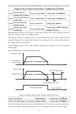
Страница 68: ...10 FDT diagram Relationship list between multi stage speed terminal and stage speed The relation between the state that multi function input terminal select multi speed terminal 4 3 2 1 and segments number of multi speed and selected goal setting is as the following table 0 represents the terminal disconnect of the corresponding function 1 represents the closed terminal of the corresponding functi...

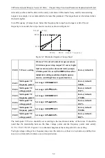
Страница 69: ...eceleration time is not selected by the input terminal switch It is used to select different acceleration and deceleration times according to the operating frequency range instead of by the S input terminal during the operation of the drive Output frequency Hz Set frequency FA 28 FA 29 Acceleration time 1 Acceleration time 0 Deceleration time 0 Deceleration time 1 Time t Figure 6 12 Schematic diag...

Страница 70: ...stall gain is used to adjust the ability of the drive to suppress over current during acceleration and deceleration The larger the value the stronger the ability to suppress over current Under the premise of no overcurrent the smaller the gain setting the better For the load with small inertia the over current stall gain should be small otherwise the dynamic response of the system will slow down F...

Страница 71: ...H 0001H Running forward 0002H Running reverse 0003H Standby status 0004H Fault status Monitoring parameters 3000H Operating frequency 0 01HZ 3001H Setting frequency 0 01HZ 3002H Bus voltage 0 1V 3003H Output voltage 1V 3004H Output current 0 1A 3005H Rotating speed 1RPM 3006H Output power 0 1 3007H Output torque 0 1 3008H Reference PID 0 1 3009H Feedback PID 0 1 300AH Terminal input remark state 3...

Страница 72: ...ommunication fault 19 Current detection circuit has fault 20 Auto learning fails 21 EEPROM operation fault 22 PID feedback disconnected fault 23 Braking kit fault 24 PID feedback stress fault 26 Motor loss protection 29 Temperature sensor disconnect fault 30 Clear the hardware latch timeout 33 Software over current during acceleration 34 Software over current during deceleration 35 Software over c...

Страница 73: ...ress Function code Read number of byte 2 n The first data high byte The first data low byte The second data high byte The second data low byte CRC Parity bit high byte CRC Parity bit high byte 01 03 04 13 88 15 18 70 07 7 4 Function Code 06 Stands for the Function Code of Writing Variable 1 The address distribution of writing parameter Function Address Data and meaning Communication control comman...

Страница 74: ...e F0 11 responds the address of 16 system is F00BH And the upper machine sends the data to AC Drive as follows Slave address Function code Parameter address high byte Parameter address low byte Data high byte Data low byte CRC Parity bit high byte CRC Parity bit low byte 01 06 F0 0B 01 2C CB 45 And the AC Drive feedback to the upper machine as follows Slave address Function code Parameter address ...

Страница 75: ...during deceleration Too short Dec time Prolong the Dec time Low AC supply voltage Use suitable dynamic braking kit Drive power is too small Select a higher power drive E006 Over current in constant speed operation Sudden change of load or abnormal Check the load or reduce the Sudden change of load Low AC supply voltage Check the AC input power supply Drive power is too small Select a higher power ...

Страница 76: ...r temperature Lower the ambient temperature Wires or connectors of control board are loose Check and rewiring Auxiliary power supply is damaged or IGBT driving voltage is too low Seek service Short circuit of IGBT bridge Seek service Control board is abnormal Seek service E017 External equipment fails Terminal SI used for inputting external faults acts Check the input of the external device E018 R...

Страница 77: ...all or detached Check the connection between motor bearing and load Drop protection point set correctly or not E029 Temperature sensor disconnect fault Poor contact of temperature sensor Check the temperature sensor wiring E030 Clear the hardware latch timeout 1 Over voltage 2 Over current 1 Over voltage fault treatment 2 Over current fault treatment E037 Keyboard STOP failure Press the stop key o...

Страница 78: ... Troubleshoot the issue Rectifier breakdown power and Troubleshoot the issue Rectifier breakdown power and motor wires connect wrongly Seek service The motor is standstill after the drive running The 3 phase outputs among U V and W are unbalance Check if damaged or obstructed Set the parameters correctly according to the nameplate No output voltage Seek service The drive display is normal after po...

Страница 79: ...15 17 19 21 A1 A2 TA0 TC0 FU A B 485 10V V1 GND SB9 9 SB1 SB10 SB2 SB4 Host Forward Host Stop Bias Start Host Reverse Grinding Program Reset SB5 Emergency HR Auxiliary Reverse KM1 KM2 KM2 SB7 23 SB3 SB6 Auxiliary Forward 380V Isolation Transformer 220V FU FU SB6 1 N 3 HR 25 27 TA1 TA0 KM1 KM2 Fault Indication Operating Indication AC380V DC Reactor 1 2 3 TC1 KM2 W V U W1 V1 U1 T3 T2 T1 T3 T2 T1 L3 ...

Страница 80: ... Appendix Appendix2 Wiring diagram of 230 vector ac drive for engineering type QF1 Host M1 Connect Brake Unit A 380V Isolation Transformer 220V Operating Indication Fault Indication TAb Start Stop Accelerate Fault Reset Decelerate Emergency N V ...

Страница 81: ...d by falling damage or improper transportation 2 4 The devices aging or failure is caused by bad environment corrosive gas or liquid 2 5 Earthquake fire wind disaster lightning abnormal voltage or other accompanied natural disasters cause the damage 2 6 Damage is caused during transport note the mode of transportation is determined by customers the company helps to handle the transferring procedur...

Отзывы: