


200 Series General Purpose Vector AC Drive Chapter 3 Mechanical and Electrical Installation
27
P
、
(+)
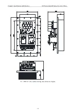
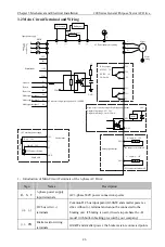
External reactor wiring
terminals outside
G132KWand bigger power, the add external reactor connect
point.
U
、
V
、
W
The AC Drive output
terminals
Connect 3-phase motor
Grounding terminal
Grounding terminal
2
、
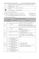
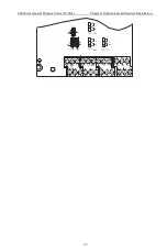
Main control circuit terminals drawing
485- 485+ 10V FM2
S1
S2
S3 S4
S5
V1 V2 GND FM1 COM COM
S6
SP1
24V
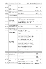
1) Function of the control terminals
The Main Control Circuit Terminals
Type
Terminal
Symbol
Terminal Name
Function
Pow
er
10V—GND
External con10v
power
P10V power for outside, Normally used as
working power of the external potentiometer,
potentiometer resistance range: 1K
Ω
~ 5K
Ω
24V—COM
External con24v
power
P24 V power for outside, generally used as the
power of digital input and output terminals and external
transducers.
Max output current: 200mA
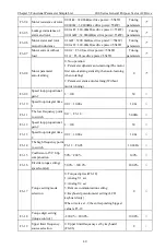
An
alo
g in
pu
t
V1—GND Analog input terminal 1
1
、
Input voltage range: DC 0V
~
10V
2
、
Input resistance: 20K
Ω
V2—GND Analog input terminal 2
1
、
Input range: DC 0V
~
10V or 4
~
20mA
Selected by jumper "JP2" on the control board.;
2
、
Input resistance: put voltage 20K
Ω
, input current
500
Ω
.
Di
git
in
pu
t
S1—COM
Multi-function digital
input terminal 1
1
、
Opto-coupler isolation;
2
、
Input resistance: 3.3K
Ω
3
、
Electrical level input voltage range:: 9V
~
30V
4
、
Programmable multi-function input.
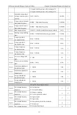
S2—COM
Multi-function digital
input terminal 2
S3—COM
Multi-function digital
input terminal 4
S4—COM
Multi-function digital
input terminal 4
S5—COM
Multi-function digital
input terminal 5
S6—COM
Multi-function digital
input terminal 6
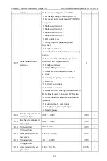
TA0
TB0
TC0
TA1
TB1 TC1