200 Series General Purpose Vector AC Drive Chapter 6 Key Functional Parameter Explanation In Detail
59
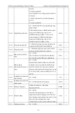
will easily overheat and the drive will be easily overcurrent. If the load is heavy and the motor starting
torque is not enough, it is recommended to increase this parameter. The torque boost can be reduced when
the load is lighter.
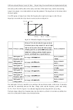
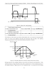
Cut-off frequency of torque boost: below this frequency,the torque boost torque is valid, if the set
frequency is exceeded, the torque boost is invalid, as shown in Figure 6-2.
Figure 6-2 Schematic diagram of torque boost
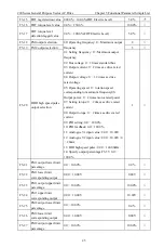
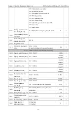
F2-00 V/F curve setting
0:Linear V/F curve(Constant torque occasion)
1:2.0 times power drop torque V/F curve( Light
load occasions such as fans and water pumps)
3:Multi-point VF curve(F2-03
~
F2-08,used for
industrial washing machines, high frequency
motors, centrifugal fans or special motors)
Factory default: 0
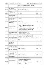
F2-03
Multi-point VF
frequency point 1
Set range: 0.00Hz
~
F0-05
Factory default:
5.00Hz
F2-04
Multi-point VF
voltage point 1
Set range: 0.0%
~
100.0%
Factory default:
15.0%
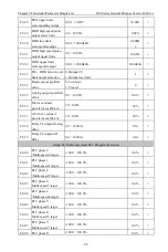
F2-05
Multi-point VF
frequency point 2
Set range: 0.00Hz
~
F0-05
Factory default:
17.50Hz
F2-06
Multi-point VF
voltage point 2
Set range: 0.0%
~
100.0%
Factory default:
45.0%
F2-07
Multi-point VF
frequency point 3
Set range: 0.00Hz
~
F0-05
Factory default:
35.00Hz
F2-08
Multi-point VF
voltage point 3
Set range: 0.0%
~
100.0%
Factory default:
80.0%
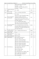
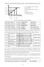
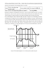
The multi-point V/F curve should be set according to the load characteristics of the motor. It should be
noted that the relationship between the three voltage points and the frequency points must satisfy:
V1<V2<V3, F1<F2<F3. Figure 6-3 is a schematic diagram of the multi-point VF curve setting.
Too high voltage setting at low frequency may cause the motor to overheat or even burn out, and the drive
may over-current stall or indicate over-current protection.
Output voltage
F0-16
F2-01
F2-02
F0-17
Output frequency

